Build - Ixox/preenfm3 GitHub Wiki
PCB v2 - March 2023
As of March 2023, the PCB version is v2 and you'll find some (small) differences.
- A small switch is pre-soldered instead of the DFU switch
- A small switch is pre-soldered for the reset button
- No more auxiliary audio
- No more 5v-3.3v jumper for the TFT. Always 5v which is what TFT are built for.
- The PCB to control board connector has been moved ans only has 1 connector of 6 pins for easier build.
- the control board has been modified. Encoder and buttons are not at the same position.
The Build
The preenfm3 comes on 2 pre-solder SMD PCBs. Presoldered but you still have to add different components.
If you plan to put your preenfm3 in a Van Daal Electronics metal enclosure, follow their guide.
Their metal case comes with all the headers, spacers and screws you need.
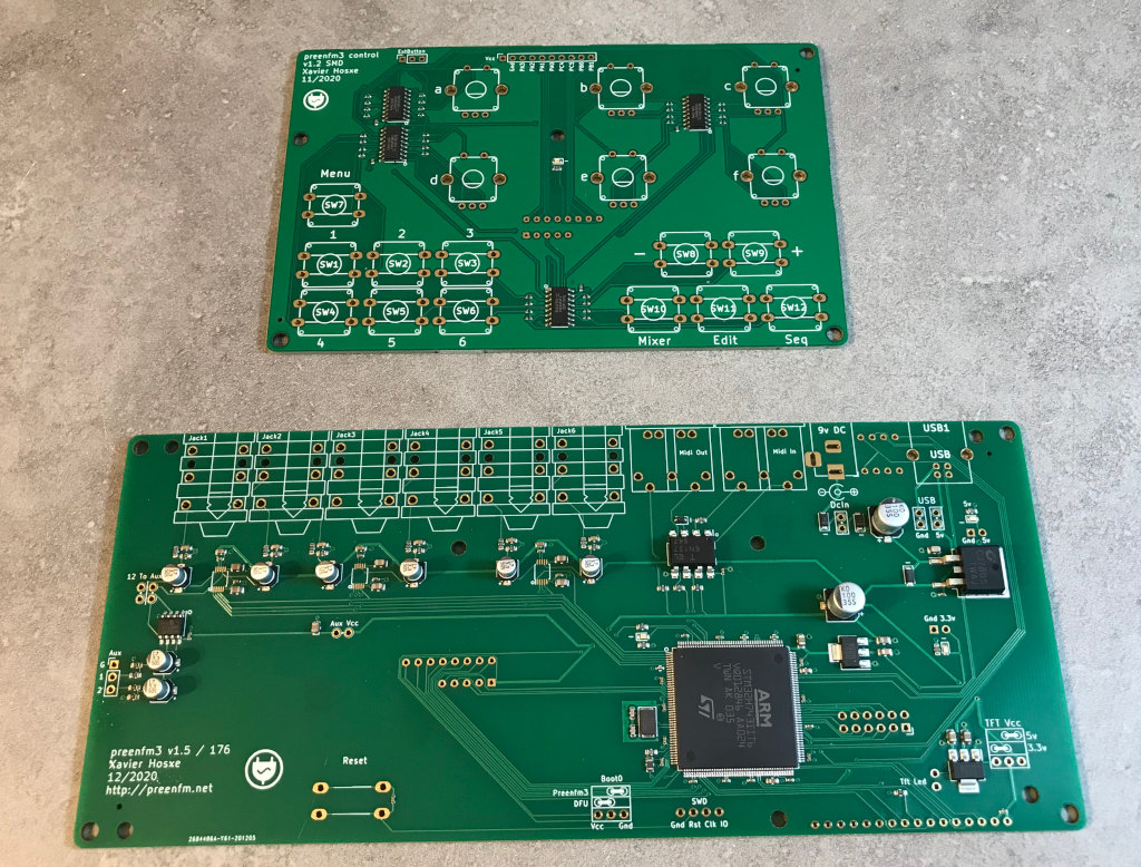
On the main PCB you need to add different headers, jumbers and solder the audio, midi, usb and dcIn sockets.
On the control board you'll have to solder encoders, and switches.
Then every thing must be put into a box.
More information about the components can be found in the BOM here.
PART 1
Here are the spacers, headers and screws you need for this 3D printed Case
This list is the same for the hybrid PCB/3DPrinted case

- : Long leg stackable headers 8 pins (PCB v2 : not needed
- (*2): Long leg stackable headers 5 pins (or 6 - 1) (PCB v2 : 6 pins)
- (*2): low profile female header zl305-20.
- (*2): M3 Hex spacers M/F 20mm * 2 - back bottom legs
- (*2): M3 Hex spacers M/F 15mm * 2 - font bottom logs
- (*5): M3 Hex spacers M/F 6mm * 5 - between main and control boards
- (*4): M3 Hex spacers F/F 14mm (12mm + nut also works) - top legs
- (*13) : M3 6mm screws (It's better if 5 of the 13 are 4mm to screw the control board).
- (*5) : M3 nuts
- : Will be cut to make some 2 and 3 pins jumpers (PCB v2 : 2 * 2 pins only)
- : 2.54mm jumpers (PCB v2 : 2 jumpers)
(1), (2), (3) and (10) should come with the PCBs you can buy on the shop. Read the description in the shop to confirm
PCB V2 : For the TFT : 15 + 4 pins.
For the control board : 6 pins
PCB V1 : The 2 zl305 (3) must be cut as follow.
You have to cut on the metal pin to make sure the adjacent pins will remain fixed in the plastic.
First cut to get the 2 TFT/SD headers.

Second cut get the 2 control board headers

Make sure the 15 pins TFT header is solder on the important pins.
Only the labeled pins on the PCB are important, so with the 15 pins header you just cut, it's expected that the right one is empty.

Here is how to use those spacers :

TFT
2.8" ili9341 TFT (dedicated TFT wiki here)
It should look like this.
Look the "2.8 TFT SPI 240x320 v1.1" (or v1.2) on the PCB and double check the dimension.
Some TFT bought on aliexpress have a reported non working SD card reader (bad wiring) and bad dimension.
I never had any problem from the ones i bought from amazon (search ILI9341 2.8)
Only 9 pins are used on the bottom header of the TFT (No touch).
The Touch is not used by the preenfm3. TFT with touch are a bit thicker and a bit less contrast.
But the touch layer makes a good protection.
If your SD card does not work, try first to resolder the SD card socket on the TFT PCB. This problem happened to several builders.
What are all those jumpers ?
In some batches, 5v and SWD contains presoldered male headers that allowed me to flash the firmware before shipping.
You shouldn't have to use.
-
DCin
Must be shorted to power the preenfm3 from the a 9V (center positive) power supply.
The goal of this jumper is to allow you to insert a switch to turn on/off your preenfm if you wish. -
USB
After some experiment, Gnd must be shorted in any case, so you can short it with a resistor leg or any metal wire.
5v don't short this jumper if you plan to power the preenfm with DCin as it will join two different 5v reference. Short it to power from the preenfm from USB. -
Boot0 (PCB v2 : presoldered switch) Must be in pfm3 mode (shorted to Gnd) most of the time.
DFU mode is used in some stuation to reflash the bootloader. Thanks to this jumper, the preenfm3 cannot be bricked whatever bad flashing you make. -
TFT VCC (Not available on PCB v2) Select 5V in most situation.
If you don't trust the tiny 3.3v convertor on your TFT PCB you can short the J1 jumper that most of them provide to make them powered by 3.3v.
Once you modified the TFT PCB, you can select 3.3V here and the 5.0v/3.3v conversion will be done on the pfm3 PCB with a higher quality 3.3v regulator.
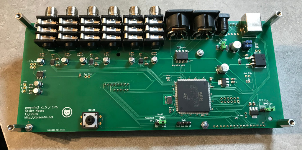
PART 2
External connections :

- Din 5 PCB mount midi jack * 2 (height<20mm see BOM or use a wire cuter)
- Neutrik NRJ6HH * 6 (audio jack) : jacks 2,4, 6 can have stereo output when respectively 1,3,5 are not plugged in.
- Usb Type B PCB sock (like this)
- DcIn socket (like this)
- A regular size SD card (Not on the picture)
Bottom view of the PCB :
April 2021 edit
The latest version of the PCB (1.6) have the DACS on external small boards.
In this case you have to cut 6 * 4 pins male headers to solder those DAC boards to the main PCB.
Follow the drawing and check the marked white pin (bottom left on the main PCB) to solder them in the correct position.

PART 3
Here is the BOM of the control surface.

Encoders can be clickable or non clickable.
The encoder click is used to quickly select active instrument, but it's optional.
Encoder click can be useful, but the click is a bit hard and there is a bit more resistance when you turn it.
- Encoders PEC12R-4220F-S0024 * 6 (PEC12R-4220F-S0012 also work). Replace S0024/S0012 by N0024/N0012 for non clickable encoders.
- Switch TL1100F160Q * 13 (12 for he control surface + 1 optional one for the reset button on the back)
- Any knobs that fits the encoders (D shaft). The ones on the picture are these ones
- e-switch serie 5j *12 (choose your color)
No particular instruction to solder this components. Just put them on the correct side of the control board.
In the center of the control board, there is a blue led that is not wired by default. You have to solder the "led" bridge. Then the led will blink in sync with the sync beat or with any external midi clock.
Control board / Main board connection
PCB V2 : the connector is a single 6 pins. It has also been moved at the bottom of the PCB for easier mount.
The space between the main board and the control board is too small (6mm) to use regular headers.
So the idea is to use the legs of the long leg headers to join the control board to the main board female headers (the plastic/header part will be cut).
Once the control board is tightly fixed with the 5 screws, it should be easy to insert the 2 headers through the female header of the main board.


Once fully inserted, you can cut the pins one by one to get rid of the plastic part.
Then, verify nothing moved and that the pins are still fully inserted. You can now solder them on the top of the control board.
Picture of the finished control board :

Part 4 / The 3D printed enclosure
Hybrid solution (PCB + 3D printed case) : information here.
100% 3D printed case: information here.