Hardware: Apex OSD - ImpulseRC/OSD GitHub Wiki
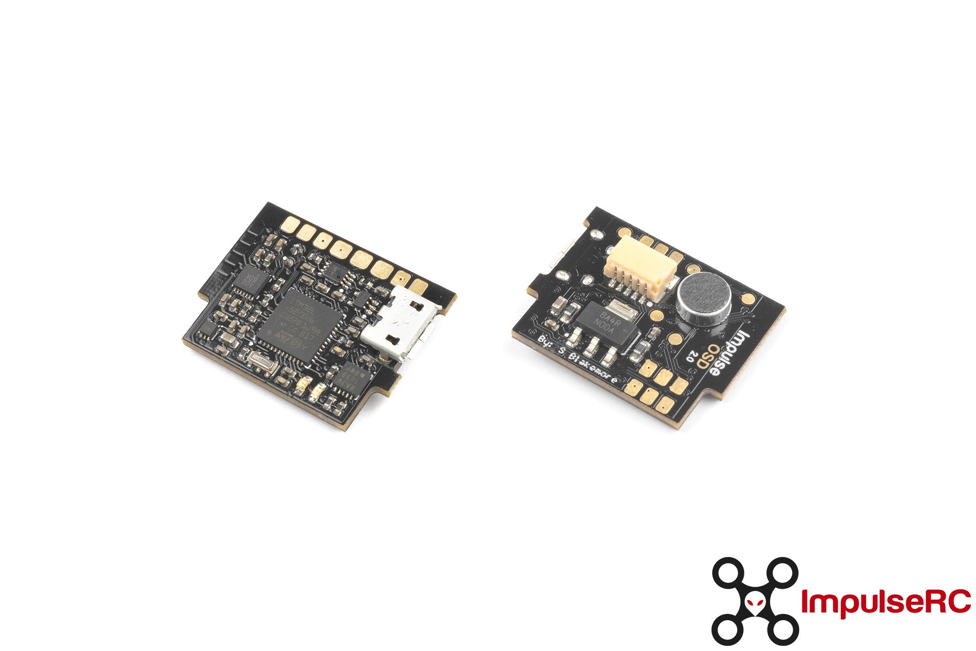
The Apex OSD for the Apex frame runs ImpulseOSD firmware introduced with the Wolf PDB. Pilots which are familiar with the Wolf PDB will feel immediately at home using the Apex OSD.
- 3S-6S battery input
- STM32L452 processor
- Fully graphical OSD - no extra OSD chip - no MAX7456 clone
- 5V camera power - using external Apex regulator board
- 5V or 7.5V VTX power - using external Apex regulator board
- Tramp Telemetry and SmartAudio support (SA up to 2.1 supported)
- Camera control
- GPS and Mag support
- LED strip support
- Microphone with AGC amplifier
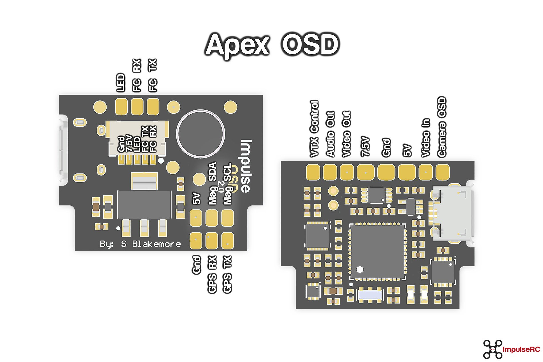
The Apex OSD is designed for the Apex frame and mounts right behind the camera in front of the second set of standoffs.
Although it is something we haven't directly tried, it should be possible to fit the Apex OSD in many other frames. To help you in making a decision as to whether this might work for you we have provided the physical outline of the board in DXF format. You should be able to print this out and test the fit.
Warning: The Apex OSD requires clean 7.5V or 5V power to operate. If you cannot fit the Apex regulator board in your build please make sure to supply it with a clean 7.5V or 5V regulator.
The Apex OSD in combination with the Apex regulator board have a single connector for communication with your flight controller and ships with a pigtail which allows plug and play operation with KISS V1+V2 and FETtec flight controllers. For Betaflight FCs you can remove the connectors from the pigtail and direct solder the serial port to your Betaflight FC.
Tip: Route the wires between the regulator and OSD away from the 4in1 ESC. Routing the wires close to the ESC can cause connection issues between OSD and FC.
Although Impulse OSD supports direct CRSF and SBUS connections for use with other FCs than KISS and Betaflight, we need to point out that the Apex OSD does not have any internal voltage or amperage sensors so you won't have any voltage or amperage information in your OSD. We did implement voltage and amperage support via CRSF but it depends on the FC you are using if it actually sends this information at an acceptable frequency.
The flight controller/receiver is automatically detected and configured, no interaction or settings are required to determine the type connected.
Apex OSD is usually powered via the Apex regulator board. The Apex regulator board requires 3S-6S Lipo voltage. The Apex OSD cannot be powered by the USB port. Alternatively you can supply 7.5V input via the pigtail (or 5V via the 5V outputs) without the Apex regulator board. To connect via USB and change settings using the desktop Config Tool you must also supply power via the 7.5V input via the pigtail or the 5V via the 5V outputs.
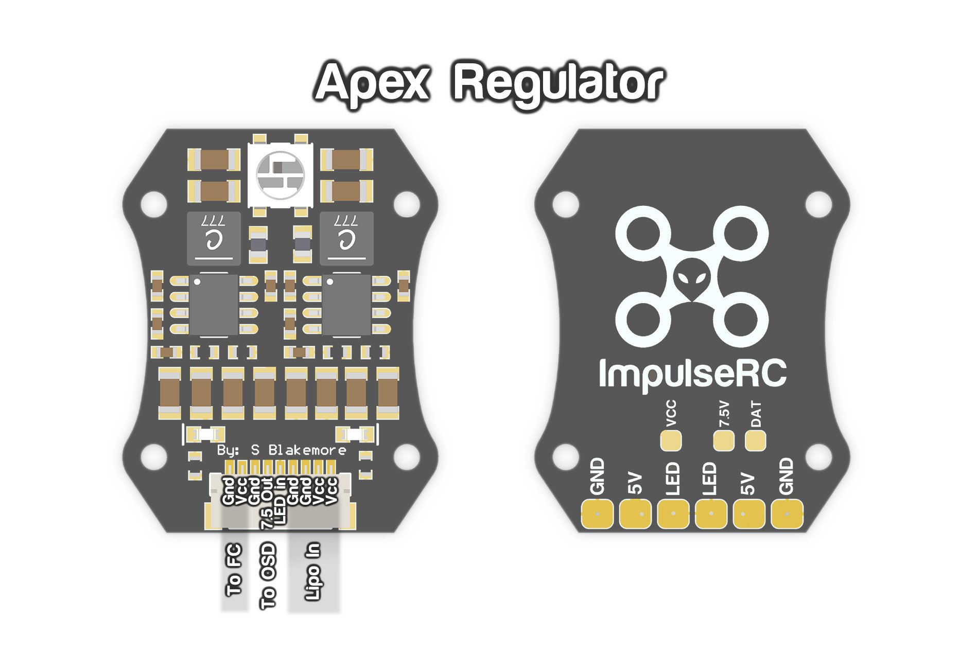
The Apex OSD is powered by the Apex regulator board featuring dual cascading switching and linear regulators to clean up the noisy power coming from the input so that you get the very best performance from your camera and video transmitter.
The 3S to 6S Lipo input feeds a 7.5V regulator with a 2.5A capacity. This in turn feeds a 5V regulator with a 1.5A capacity. In out testing this is more than enough to power any standard FPV camera and video transmitter, GPS as well as the optional LEDs for the Apex frame. We do not recommend powering extra devices from the regulator board as you are at risk of overloading the regulators, this includes cameras such as the Runcam Split series which have high current requirements.
If you would like to ease the load on the 5V regulator and create some more headroom we recommend running an HV video transmitter from the 7.5V rail.
We strongly recommend that you power your VTX from the power outputs on the PDB, as well as also powering your camera directly from the dedicated camera power outputs on the PDB. Trying to power your video transmitter from Lipo power or powering your camera from the 5V output of your video transmitter can give undesirable results in certain situations.
Even more important for the cleanest video possible is soldering both the VTX and camera GND to the common GND pad on the Apex OSD!
The Apex OSD is shipped with an electret microphone already soldered to the Apex OSD board.
For the best audio performance it is highly recommended that you block the microphone from direct airflow. The preferred way to do this is by using a piece of open cell foam. Another method is to use one of the red plastic caps which commonly come as protective packaging on SMA connectors. The mounting behind the camera in the Apex frame should prevent most airflow noise.
For classic camera control the Apex OSD has a dedicated true analog output. This allows you to control the OSD embedded in your camera and change camera settings in the field.
Via the same camera control pad the Apex OSD also features a serial port specifically for the newer generation of camera with digital control. This includes controlling recording of the Runcam Split as well as many other camera via the Runcam control adapter.
To get the full video transmitter control features of ImpulseOSD it's important to connect your Unify SmartAudio or Tramp Telemetry wire directly to the Apex OSD and not to your flight controller!
Please connect your video transmitter control wire to the TX pad of the dedicated VTX serial port on the Apex OSD. The video transmitter is automatically detected and configured, no interaction or settings are required to determine the type connected.
SmartAudio and Audio: Most SmartAudio VTX devices only have one cable for SmartAudio and Audio. In that case simple strip off the SmartAudio cable a bit longer and solder it across both the VTX and Audio pad on the Apex OSD.
The Apex OSD has a comprehensive set of GPS enabled features that work across both KISS and Betaflight.
You can connect the GPS either directly to the Apex OSD or to your flight controller (KISS only on newer FW versions). ImpulseOSD will intelligently detect your configuration and display GPS data as usual. However we strongly recommend that you connect the GPS to the Apex OSD, this will enable the best performance of the OSD features as well as remove any extra processing load from your flight controller. GPS data will be served to the flight controller automatically so you can see the GPS information in your radio or use GPS rescue features.
The Apex OSD also supports GPS devices with an included Magnetometer. In certain situations this should give a more accurate and responsive home arrow and compass display, however all GPS related features are fully working without a Magnetometer connected (for some features it is recommended).
Barometers are also supported. A Barometer will give you more responsive and accurate altitude measurements (vs. the GPS) and also give you a temperature reading you can display in the OSD.
The Apex OSD has two status LEDs. The green LED is directly connected to the 5V power and should always be lit when a Lipo is connected.
The red LED should be flashing in a one second rhythm (we call it the "heartbeat"). That means everything is OK and the OSD loop is running normally.
If it does not flash or is off or on, the OSD loop does not run.
If it flashes in an irregular rhythm it is looking for a flight controller connection or the connection to the flight controller has been interrupted.