Cables - IanSB/RGBtoHDMI GitHub Wiki
NOTE: Always ensure that cables are connected before powering on your system and the converter and never plug or unplug cables with the power on.
16 way (12 bit extender) or 12 way (RGBtoHDMI main board) IDC header to TTL computer connections
Note: 3 bit RGB TTL computers like the BBC micro, Oric/Atmos, QL or Camputers Lynx can also be connected via the 6 way IDC on the analog board or 3 bit TTL buffer board. (See below)
For connections using the 10 way header on the old 6 bit design visit here: old 6 bit connections
BBC micro / Master 128 / Electron (3 bit RGB TTL)
| 12 Bit Extender 16 way IDC | RGBtoHDMI 12 way IDC | 6 way DIN | Notes |
|---|---|---|---|
| Pin 1 green0 | |||
| Pin 2 red0 | |||
| Pin 3 blue0 | |||
| Pin 4 green1 | |||
| Pin 5 red1 | Pin 1 red1 | ||
| Pin 6 blue1 | Pin 2 blue 1 | ||
| Pin 7 GND | Pin 3 GND | Pin 5 | |
| Pin 8 green2 | Pin 4 green2 | ||
| Pin 9 red2 | Pin 5 red2 | ||
| Pin 10 blue2 | Pin 6 blue2 | ||
| Pin 11 RED3 | Pin 7 RED3 | Pin 1 | |
| Pin 12 HSYNC | Pin 8 HSYNC | Pin 4 | |
| Pin 13 GREEN3 | Pin 9 GREEN3 | Pin 2 | |
| Pin 14 VSYNC | Pin 10 VSYNC | ||
| Pin 15 BLUE3 | Pin 11 BLUE3 | Pin 3 | |
| Pin 16 +5V | Pin 12 +5V | Pin 6 | Leave unconnected if powering Pi externally |
Spectrum 128 or +2 (grey) and QL (4 bit RGBI TTL)
| 12 Bit Extender 16 way IDC | RGBtoHDMI 12 way IDC | 8 way DIN | Notes |
|---|---|---|---|
| Pin 1 green0 | |||
| Pin 2 red0 | |||
| Pin 3 blue0 | |||
| Pin 4 green1 | |||
| Pin 5 red1 | Pin 1 red1 | ||
| Pin 6 blue1 | Pin 2 blue 1 | ||
| Pin 7 GND | Pin 3 GND | Pin 2 | |
| Pin 8 green2 | Pin 4 green2 | Pin 3 | Intensity |
| Pin 9 red2 | Pin 5 red2 | ||
| Pin 10 blue2 | Pin 6 blue2 | ||
| Pin 11 RED3 | Pin 7 RED3 | Pin 7 | |
| Pin 12 HSYNC | Pin 8 HSYNC | Pin 4 | |
| Pin 13 GREEN3 | Pin 9 GREEN3 | Pin 6 | |
| Pin 14 VSYNC | Pin 10 VSYNC | ||
| Pin 15 BLUE3 | Pin 11 BLUE3 | Pin 8 | |
| Pin 16 +5V | Pin 12 +5V |
Note the green2 / intensity pin is not used on the QL as it is only 3 bit TTL but the same cable can be used
Oric 1 / Atmos (3 bit RGB TTL)
| 12 Bit Extender 16 way IDC | RGBtoHDMI 12 way IDC | 5 way 180° DIN | Notes |
|---|---|---|---|
| Pin 1 green0 | |||
| Pin 2 red0 | |||
| Pin 3 blue0 | |||
| Pin 4 green1 | |||
| Pin 5 red1 | Pin 1 red1 | ||
| Pin 6 blue1 | Pin 2 blue 1 | ||
| Pin 7 GND | Pin 3 GND | Pin 5 | |
| Pin 8 green2 | Pin 4 green2 | ||
| Pin 9 red2 | Pin 5 red2 | ||
| Pin 10 blue2 | Pin 6 blue2 | ||
| Pin 11 RED3 | Pin 7 RED3 | Pin 1 | |
| Pin 12 HSYNC | Pin 8 HSYNC | Pin 4 | |
| Pin 13 GREEN3 | Pin 9 GREEN3 | Pin 2 | |
| Pin 14 VSYNC | Pin 10 VSYNC | ||
| Pin 15 BLUE3 | Pin 11 BLUE3 | Pin 3 | |
| Pin 16 +5V | Pin 12 +5V |
Camputers Lynx (3 bit RGB TTL)
| 12 Bit Extender 16 way IDC | RGBtoHDMI 12 way IDC | 5 way 240° DIN | Notes |
|---|---|---|---|
| Pin 1 green0 | |||
| Pin 2 red0 | |||
| Pin 3 blue0 | |||
| Pin 4 green1 | |||
| Pin 5 red1 | Pin 1 red1 | ||
| Pin 6 blue1 | Pin 2 blue 1 | ||
| Pin 7 GND | Pin 3 GND | Shield | Must be connected to both shield halves |
| Pin 8 green2 | Pin 4 green2 | ||
| Pin 9 red2 | Pin 5 red2 | ||
| Pin 10 blue2 | Pin 6 blue2 | ||
| Pin 11 RED3 | Pin 7 RED3 | Pin 5 | |
| Pin 12 HSYNC | Pin 8 HSYNC | Pin 1 | |
| Pin 13 GREEN3 | Pin 9 GREEN3 | Pin 4 | |
| Pin 14 VSYNC | Pin 10 VSYNC | ||
| Pin 15 BLUE3 | Pin 11 BLUE3 | Pin 2 | |
| Pin 16 +5V | Pin 12 +5V |
Note the 5 way 240° DIN has different pin numbering to the 5 way 180° DIN
Sharp MZ700 + MZ1500 (3 bit RGB TTL) & Sharp MZ800 (4 bit RGB TTL)
| 12 Bit Extender 16 way IDC | RGBtoHDMI 12 way IDC | 8 way DIN | Notes |
|---|---|---|---|
| Pin 1 green0 | |||
| Pin 2 red0 | |||
| Pin 3 blue0 | |||
| Pin 4 green1 | |||
| Pin 5 red1 | Pin 1 red1 | ||
| Pin 6 blue1 | Pin 2 blue 1 | ||
| Pin 7 GND | Pin 3 GND | Pin 2 | |
| Pin 8 green2 | Pin 4 green2 | Pin 1 | Intensity |
| Pin 9 red2 | Pin 5 red2 | ||
| Pin 10 blue2 | Pin 6 blue2 | ||
| Pin 11 RED3 | Pin 7 RED3 | Pin 6 | R |
| Pin 12 HSYNC | Pin 8 HSYNC | Pin 4 | HSYNC |
| Pin 13 GREEN3 | Pin 9 GREEN3 | Pin 7 | G |
| Pin 14 VSYNC | Pin 10 VSYNC | Pin 5 | VSYNC |
| Pin 15 BLUE3 | Pin 11 BLUE3 | Pin 8 | B |
| Pin 16 +5V | Pin 12 +5V |
Note previously the MZ700 cable used composite sync on Pin 3 of the 8 way DIN connected to HSYNC but that won't work on the MZ800 as it was omitted on that system.
This new arrangement using separate sync will work on all the above Sharp computers (The intensity input is only used by the MZ800 profile and is ignored by the other profiles)
Intellivision (4 bit TTL)
| 12 Bit Extender 16 way IDC | RGBtoHDMI 12 way IDC | AY-3-8900 chip | Notes |
|---|---|---|---|
| Pin 1 green0 | |||
| Pin 2 red0 | |||
| Pin 3 blue0 | |||
| Pin 4 green1 | |||
| Pin 5 red1 | Pin 1 red1 | ||
| Pin 6 blue1 | Pin 2 blue 1 | ||
| Pin 7 GND | Pin 3 GND | AY-3-8900 Pin 1 | Vss on AY-3-8900 |
| Pin 8 green2 | Pin 4 green2 | AY-3-8900 Pin 16 | V4 on AY-3-8900 |
| Pin 9 red2 | Pin 5 red2 | ||
| Pin 10 blue2 | Pin 6 blue2 | ||
| Pin 11 RED3 | Pin 7 RED3 | AY-3-8900 Pin 22 | V1 on AY-3-8900 |
| Pin 12 HSYNC | Pin 8 HSYNC | AY-3-8900 Pin 19 | V5 on AY-3-8900 |
| Pin 13 GREEN3 | Pin 9 GREEN3 | AY-3-8900 Pin 21 | V2 on AY-3-8900 |
| Pin 14 VSYNC | Pin 10 VSYNC | ||
| Pin 15 BLUE3 | Pin 11 BLUE3 | AY-3-8900 Pin 18 | V3 on AY-3-8900 |
| Pin 16 +5V | Pin 12 +5V |
IBM PC MDA, CGA, EGA (2, 4 or 6 bit TTL) / Olivetti Prodest PC1 (4 bit RGBI TTL) / Commodore 128 80 column (4 bit RGBI TTL)
| 12 Bit Extender 16 way IDC | RGBtoHDMI 12 way IDC | 9 way D-Type | Notes |
|---|---|---|---|
| Pin 1 green0 | |||
| Pin 2 red0 | |||
| Pin 3 blue0 | |||
| Pin 4 green1 | |||
| Pin 5 red1 | Pin 1 red1 | ||
| Pin 6 blue1 | Pin 2 blue 1 | ||
| Pin 7 GND | Pin 3 GND | Pin 1 | |
| Pin 8 green2 | Pin 4 green2 | Pin 6 | Intensity in CGA / MDA |
| Pin 9 red2 | Pin 5 red2 | Pin 2 | |
| Pin 10 blue2 | Pin 6 blue2 | Pin 7 | Video in MDA |
| Pin 11 RED3 | Pin 7 RED3 | Pin 3 | |
| Pin 12 HSYNC | Pin 8 HSYNC | Pin 8 | |
| Pin 13 GREEN3 | Pin 9 GREEN3 | Pin 4 | |
| Pin 14 VSYNC | Pin 10 VSYNC | Pin 9 | |
| Pin 15 BLUE3 | Pin 11 BLUE3 | Pin 5 | |
| Pin 16 +5V | Pin 12 +5V | N/C |
Note: You can use a straight through IDC ribbon to a 9 way IDC D type connector connected to ribbon from GND to BLUE3
Sam Coupe (7 bit RrGgBbI TTL)
| 12 Bit Extender 16 way IDC | RGBtoHDMI 12 way IDC | Euroconnector | Notes |
|---|---|---|---|
| Pin 1 green0 | |||
| Pin 2 red0 | |||
| Pin 3 blue0 | |||
| Pin 4 green1 | |||
| Pin 5 red1 | Pin 1 red1 | 31A | BRIGHT |
| Pin 6 blue1 | Pin 2 blue 1 | ||
| Pin 7 GND | Pin 3 GND | 32C | 0 VOLTS |
| Pin 8 green2 | Pin 4 green2 | 31C | GREEN0 |
| Pin 9 red2 | Pin 5 red2 | 30A | RED0 |
| Pin 10 blue2 | Pin 6 blue2 | 29A | BLUE0 |
| Pin 11 RED3 | Pin 7 RED3 | 25A | RED1 |
| Pin 12 HSYNC | Pin 8 HSYNC | 27A | CSYNC |
| Pin 13 GREEN3 | Pin 9 GREEN3 | 26A | GREEN1 |
| Pin 14 VSYNC | Pin 10 VSYNC | ||
| Pin 15 BLUE3 | Pin 11 BLUE3 | 26C | BLUE1 |
| Pin 16 +5V | Pin 12 +5V | 32A | +5V |
(Elan) Enterprise (8 bit RrrGggBb TTL)
| 12 Bit Extender 16 way IDC | RGBtoHDMI 12 way IDC | Internal IC | Notes |
|---|---|---|---|
| Pin 1 green0 | |||
| Pin 2 red0 | |||
| Pin 3 blue0 | |||
| Pin 4 green1 | |||
| Pin 5 red1 | Pin 1 red1 | IC33 Pin 5 | |
| Pin 6 blue1 | Pin 2 blue 1 | IC33 Pin 14 | same as blue3 |
| Pin 7 GND | Pin 3 GND | IC33 Pin 10 | 0 VOLTS |
| Pin 8 green2 | Pin 4 green2 | IC33 Pin 9 | |
| Pin 9 red2 | Pin 5 red2 | IC33 Pin 12 | |
| Pin 10 blue2 | Pin 6 blue2 | IC33 Pin 7 | |
| Pin 11 RED3 | Pin 7 RED3 | IC33 Pin 18 | |
| Pin 12 HSYNC | Pin 8 HSYNC | >IC32 Pin 8< | CSYNC on different chip |
| Pin 13 GREEN3 | Pin 9 GREEN3 | IC33 Pin 16 | |
| Pin 14 VSYNC | Pin 10 VSYNC | IC33 Pin 3 | GREEN1 in 9bpp (Vsync) mode |
| Pin 15 BLUE3 | Pin 11 BLUE3 | IC33 Pin 14 | same as blue1 |
| Pin 16 +5V | Pin 12 +5V | IC33 Pin 20 | +5V |
Apple IIc digital interface (1 + 1 bit TTL)
This is preferred to connecting using the analog composite video interface as the 4 lines of text in mixed text and graphics mode will be displayed without artifacts.
| 12 Bit Extender 16 way IDC | RGBtoHDMI 12 way IDC | 15 way D-Type | Notes |
|---|---|---|---|
| Pin 1 green0 | |||
| Pin 2 red0 | |||
| Pin 3 blue0 | |||
| Pin 4 green1 | |||
| Pin 5 red1 | Pin 1 red1 | ||
| Pin 6 blue1 | Pin 2 blue 1 | ||
| Pin 7 GND | Pin 3 GND | Pin 13 | GND |
| Pin 8 green2 | Pin 4 green2 | Pin 10 | GR - switches graphics on |
| Pin 9 red2 | Pin 5 red2 | ||
| Pin 10 blue2 | Pin 6 blue2 | ||
| Pin 11 RED3 | Pin 7 RED3 | ||
| Pin 12 HSYNC | Pin 8 HSYNC | Pin 3 | SYNC - Composite sync |
| Pin 13 GREEN3 | Pin 9 GREEN3 | Pin 11 | SEROUT - TTL inverted video |
| Pin 14 VSYNC | Pin 10 VSYNC | ||
| Pin 15 BLUE3 | Pin 11 BLUE3 | ||
| Pin 16 +5V | Pin 12 +5V | N/C |
Apple IIe digital interface internal pickup (1 + 1 bit TTL)
This is preferred to connecting using the analog composite video interface as the 4 lines of text in mixed text and graphics mode will be displayed without artifacts.
| 12 Bit Extender 16 way IDC | RGBtoHDMI 12 way IDC | Motherboard | Notes |
|---|---|---|---|
| Pin 1 green0 | |||
| Pin 2 red0 | |||
| Pin 3 blue0 | |||
| Pin 4 green1 | |||
| Pin 5 red1 | Pin 1 red1 | ||
| Pin 6 blue1 | Pin 2 blue 1 | ||
| Pin 7 GND | Pin 3 GND | UF5 166 pin 8 | 74166 GND |
| Pin 8 green2 | Pin 4 green2 | UE5 344-002x pin 2 | IOU GR - switches graphics on |
| Pin 9 red2 | Pin 5 red2 | ||
| Pin 10 blue2 | Pin 6 blue2 | ||
| Pin 11 RED3 | Pin 7 RED3 | ||
| Pin 12 HSYNC | Pin 8 HSYNC | UE5 344-002x pin 39 | IOU SYNC - Composite sync |
| Pin 13 GREEN3 | Pin 9 GREEN3 | UF5 166 pin 1 or pin 13 | 74166 SEROUT - TTL inverted video |
| Pin 14 VSYNC | Pin 10 VSYNC | ||
| Pin 15 BLUE3 | Pin 11 BLUE3 | ||
| Pin 16 +5V | Pin 12 +5V | UF5 166 pin 16 | 74166 +5V leave unconnected if powering Pi externally |
Apple II / II+ digital interface internal pickup (1 + 1 bit TTL)
This is preferred to connecting using the analog composite video interface as the 4 lines of text in mixed text and graphics mode will be displayed without artifacts.
| 12 Bit Extender 16 way IDC | RGBtoHDMI 12 way IDC | Motherboard | Notes |
|---|---|---|---|
| Pin 1 green0 | |||
| Pin 2 red0 | |||
| Pin 3 blue0 | |||
| Pin 4 green1 | |||
| Pin 5 red1 | Pin 1 red1 | ||
| Pin 6 blue1 | Pin 2 blue 1 | ||
| Pin 7 GND | Pin 3 GND | chip B10 pin 7 | GND |
| Pin 8 green2 | Pin 4 green2 | chip B13 pin 13 | switches graphics on |
| Pin 9 red2 | Pin 5 red2 | ||
| Pin 10 blue2 | Pin 6 blue2 | ||
| Pin 11 RED3 | Pin 7 RED3 | ||
| Pin 12 HSYNC | Pin 8 HSYNC | chip C13 Pin 8 | Composite sync |
| Pin 13 GREEN3 | Pin 9 GREEN3 | chip B10 pin 5 | Video output |
| Pin 14 VSYNC | Pin 10 VSYNC | ||
| Pin 15 BLUE3 | Pin 11 BLUE3 | ||
| Pin 16 +5V | Pin 12 +5V | Chip B10 pin 14 | +5V leave unconnected if powering Pi externally |
Apple IIGS (12 bit RGB TTL)
| 12 Bit Extender 16 way IDC | Motherboard | Notes |
|---|---|---|
| Pin 1 green0 | H3 Pin 5 | |
| Pin 2 red0 | H4 Pin 5 | |
| Pin 3 blue0 | H2 Pin 5 | |
| Pin 4 green1 | H3 Pin 4 | |
| Pin 5 red1 | H4 Pin 4 | |
| Pin 6 blue1 | H2 Pin 4 | |
| Pin 7 GND | H3 Pin 7 | |
| Pin 8 green2 | H3 Pin 3 | |
| Pin 9 red2 | H4 Pin 3 | |
| Pin 10 blue2 | H2 Pin 3 | |
| Pin 11 RED3 | H4 Pin 2 | |
| Pin 12 HSYNC | H1 Pin 3 | |
| Pin 13 GREEN3 | H3 Pin 2 | |
| Pin 14 VSYNC | UF3 Pin 2 (74F86) | Flip 6 Also available on VGC Pin 49 and TP24 |
| Pin 15 BLUE3 | H2 Pin 2 | |
| Pin 16 +5V | H1 Pin 10 | Leave unconnected if powering Pi externally |
Atari ST 40 pin shifter (9 bit RGB TTL + mono TTL)
| 12 Bit Extender 16 way IDC | Motherboard | Notes |
|---|---|---|
| Pin 1 green0 | Shifter40 pin 26 | G0 |
| Pin 2 red0 | Shifter40 pin 29 | R0 |
| Pin 3 blue0 | Shifter40 pin 23 | B0 |
| Pin 4 green1 | Shifter40 pin 25 | G1 |
| Pin 5 red1 | Shifter40 pin 28 | R1 |
| Pin 6 blue1 | Shifter40 pin 22 | B1 |
| Pin 7 GND | Shifter40 pin 20 | |
| Pin 8 green2 | Shifter40 pin 24 | G2 |
| Pin 9 red2 | Shifter40 pin 27 | R2 |
| Pin 10 blue2 | Shifter40 pin 21 | B2 |
| Pin 11 RED3 | N/C | |
| Pin 12 HSYNC | Glue pin 37 | Also on modulator connector pin 5 |
| Pin 13 GREEN3 | Shifter40 pin 30 | MONO |
| Pin 14 VSYNC | Glue pin 38 | Also on modulator connector pin 4 |
| Pin 15 BLUE3 | Glue pin 36 | BLANK Also on diodes near shifter |
| Pin 16 +5V | Shifter40 Pin 40 | Leave unconnected if powering Pi externally |
Photos showing connections on an Atari STFM using the 40 pin ST shifter pickup board. Other ST models may require different pickup points for the Hsync, Vsync and Blank signals:
images/cables/ataristfm1.jpg
images/cables/ataristfm2.jpg
This photo shows the optional use of a cable mounted header so the external cable can be detached rather than having a permanently attached captive cable:
images/cables/ataristfm3.jpg
Atari STE 84 pin shifter (12 bit RGB TTL + mono TTL)
There is a problem with bit ordering due to the way that the STE schematic numbered the bits.
On RGBtoHDMI the bits are R3, R2, R1, R0 ; G3, G2, G1, G0 ; B3, B2, B1, B0 with the '3' being the most significant bit and '0' being the least significant bit.
On the ST there were only 3 bits each of RGB and they were numbered R2, R1, R0 and they could be mapped easily to the existing RGB inputs with the same order.
However on the STE an extra bit for each of RGB was added and this was the least significant bit but it was named R3, G3, B3 so the bit ordering is messed up. This may have been done so that the most significant 3 bits matched the ST but it meant that the bit order was R2, R1, R0, R3 etc. which means that the Rx Gx Bx bits cannot be mapped directly.
The correct order is RGBtoHDMI R3, R2, R1, R0 to STE R2, R1, R0, R3 etc:
| 12 Bit Extender 16 way IDC | Motherboard | Notes |
|---|---|---|
| Pin 1 green0 | Shifter84 pin 42 | shifter G3 |
| Pin 2 red0 | Shifter84 pin 38 | shifter R3 |
| Pin 3 blue0 | Shifter84 pin 46 | shifter B3 |
| Pin 4 green1 | Shifter84 pin 45 | shifter G0 |
| Pin 5 red1 | Shifter84 pin 41 | shifter R0 |
| Pin 6 blue1 | Shifter84 pin 49 | shifter B0 |
| Pin 7 GND | Shifter84 pin 74 or 75 | |
| Pin 8 green2 | Shifter84 pin 44 | shifter G1 |
| Pin 9 red2 | Shifter84 pin 40 | shifter R1 |
| Pin 10 blue2 | Shifter84 pin 48 | shifter B1 |
| Pin 11 RED3 | Shifter84 pin 39 | shifter R2 |
| Pin 12 HSYNC | U211C pin 6 (74LS04) | Composite sync: Also on U403 (MC1377) Pin 2 |
| Pin 13 GREEN3 | Shifter84 pin 43 | shifter G2 |
| Pin 14 VSYNC | Shifter84 pin 50 | MONO |
| Pin 15 BLUE3 | Shifter84 pin 47 | shifter B2 |
| Pin 16 +5V | Shifter84 Pin 11 or 32 | Leave unconnected if powering Pi externally |
It is probably easier to solder the RGB lines to the ends of the resistors connected to the shifter so the easiest way to avoid confusion is to go by resistor values:
The smallest value RGB resistors (1.5K) are connected to RGBtoHDMI R3, G3, B3
The next largest value RGB resistors (3K) are connected to RGBtoHDMI R2, G2, B2
The next largest value RGB resistors (6.2K) are connected to RGBtoHDMI R1, G1, B1
The largest RGB resistor values (12k) are connected to RGBtoHDMI R0, G0, B0
Use an STE diagnostic cartridge or program to display RGB colour gradients which should show if the connections are correct
Amiga 48 pin Denise chip pickup (12 bit RGB TTL)
This shows the external version of Amiga RGBtoHDMI using the Denise pickup board:
This Denise chip is plugged into this board and then that is plugged into the Denise socket:
images/cables/amiga1.jpg
You can either run a 16 way cable directly to the external 12 bit RGBtoHDMI or use two separate cables with a cable mounted socket as shown below:
images/cables/amiga2.jpg
THis shows the cable plugged into the external 12 bit RGBtoHDMI:
images/cables/amiga3.jpg
6 way IDC (Analog interface or 3 bit TTL buffer) to computer connections
Note: The TTL computers will also work with the analog interface
BBC micro / Master 128 / Electron (3 bit RGB TTL)
| RGBtoHDMI 6 way IDC | 6 way DIN | Notes |
|---|---|---|
| Pin 1 GND | Pin 5 | |
| Pin 2 SYNC | Pin 4 | |
| Pin 3 BLUE | Pin 3 | |
| Pin 4 GREEN | Pin 2 | |
| Pin 5 RED | Pin 1 | |
| Pin 6 +5V | Pin 6 | Leave unconnected if powering Pi externally |
Amstrad CPC (Analog RGB - same as BBC except power)
| RGBtoHDMI 6 way IDC | 6 way DIN | Notes |
|---|---|---|
| Pin 1 GND | Pin 5 | |
| Pin 2 SYNC | Pin 4 | |
| Pin 3 BLUE | Pin 3 | |
| Pin 4 GREEN | Pin 2 | |
| Pin 5 RED | Pin 1 | |
| Pin 6 +5V | N/C |
Spectrum +2 (grey), +2A, +3 and Sinclair QL (Analog RGB)
| RGBtoHDMI 6 way IDC | 8 way DIN | Notes |
|---|---|---|
| Pin 1 GND | Pin 2 | |
| Pin 2 SYNC | Pin 4 | |
| Pin 3 BLUE | Pin 8 | |
| Pin 4 GREEN | Pin 6 | |
| Pin 5 RED | Pin 7 | |
| Pin 6 +5V | N/C |
Spectrum 128 can be used with the analog board by connecting three 1N4148 diodes from the intensity DIN pin 3 to each of the RGB pins (DIN pins 6,7,8) with banded ends of the diodes towards to pin 3 of the 8 way DIN)
Oric 1 / Atmos (3 bit RGB TTL)
| RGBtoHDMI 6 way IDC | 5 way 180° DIN | Notes |
|---|---|---|
| Pin 1 GND | Pin 5 | |
| Pin 2 SYNC | Pin 4 | |
| Pin 3 BLUE | Pin 3 | |
| Pin 4 GREEN | Pin 2 | |
| Pin 5 RED | Pin 1 | |
| Pin 6 +5V | N/C |
Camputers Lynx (3 bit RGB TTL)
| RGBtoHDMI 6 way IDC | 5 way 240° DIN | Notes |
|---|---|---|
| Pin 1 GND | Shield | Must be connected to both shield halves |
| Pin 2 SYNC | Pin 1 | |
| Pin 3 BLUE | Pin 2 | |
| Pin 4 GREEN | Pin 4 | |
| Pin 5 RED | Pin 5 | |
| Pin 6 +5V | N/C |
Note the 5 way 240° DIN has different pin numbering to the 5 way 180° DIN
Sharp MZ700 + MZ1500 (3 bit RGB TTL)
| RGBtoHDMI 6 way IDC | 8 way DIN | Notes |
|---|---|---|
| Pin 1 GND | Pin 2 | |
| Pin 2 SYNC | Pin 3 | composite sync |
| Pin 3 BLUE | Pin 8 | |
| Pin 4 GREEN | Pin 7 | |
| Pin 5 RED | Pin 6 | |
| Pin 6 +5V | N/C |
Note this cable will not work with the MZ800 because that is RGBI and dropped composite sync from the connector
Tandy color computer 3 (Analog RGB)
| RGBtoHDMI 6 way IDC | 10 way IDC | Notes |
|---|---|---|
| Pin 1 GND | Pin 1 or 2 | |
| Pin 2 SYNC | banded ends of diode pair from Pins 8 & 9 | |
| Pin 3 BLUE | Pin 5 | Blue |
| Pin 4 GREEN | Pin 4 | Green |
| Pin 5 RED | Pin 3 | Red |
| Pin 6 +5V | N/C |
The RGB connector on the CoCo 3 has separate H & V sync but the analog input expects composite sync so you must diode OR the two sync signals together:
Connect the unbanded ends of two 1N4148 diodes to Pin 8 and Pin 9 of the CoCo RGB connector
Connect the banded ends of both diodes to the Pin 2 SYNC input of RGBtoHDMI
48K Spectrum (Analog YUV)
| RGBtoHDMI 6 way IDC | Spectrum Edge Connector | Notes |
|---|---|---|
| Pin 1 GND | 14B | |
| Pin 2 SYNC | 16B | same as Y |
| Pin 3 U | 18B | |
| Pin 4 Y | 16B | |
| Pin 5 V | 17B | |
| Pin 6 +5V | N/C |
Note Some Issue 1 or 2 Boards may require links fitted to bring YUV to the edge connector
Atom (Analog YUV)
| RGBtoHDMI 6 way IDC | 10 way IDC | Notes |
|---|---|---|
| Pin 1 GND | Pin 10 | |
| Pin 2 SYNC | Pin 8 | HS |
| Pin 3 U | Pin 7 | PB |
| Pin 4 Y | Pin 9 | Video |
| Pin 5 V | Pin 3 | PA |
| Pin 6 +5V | Pin 2 | Leave unconnected if powering Pi externally |
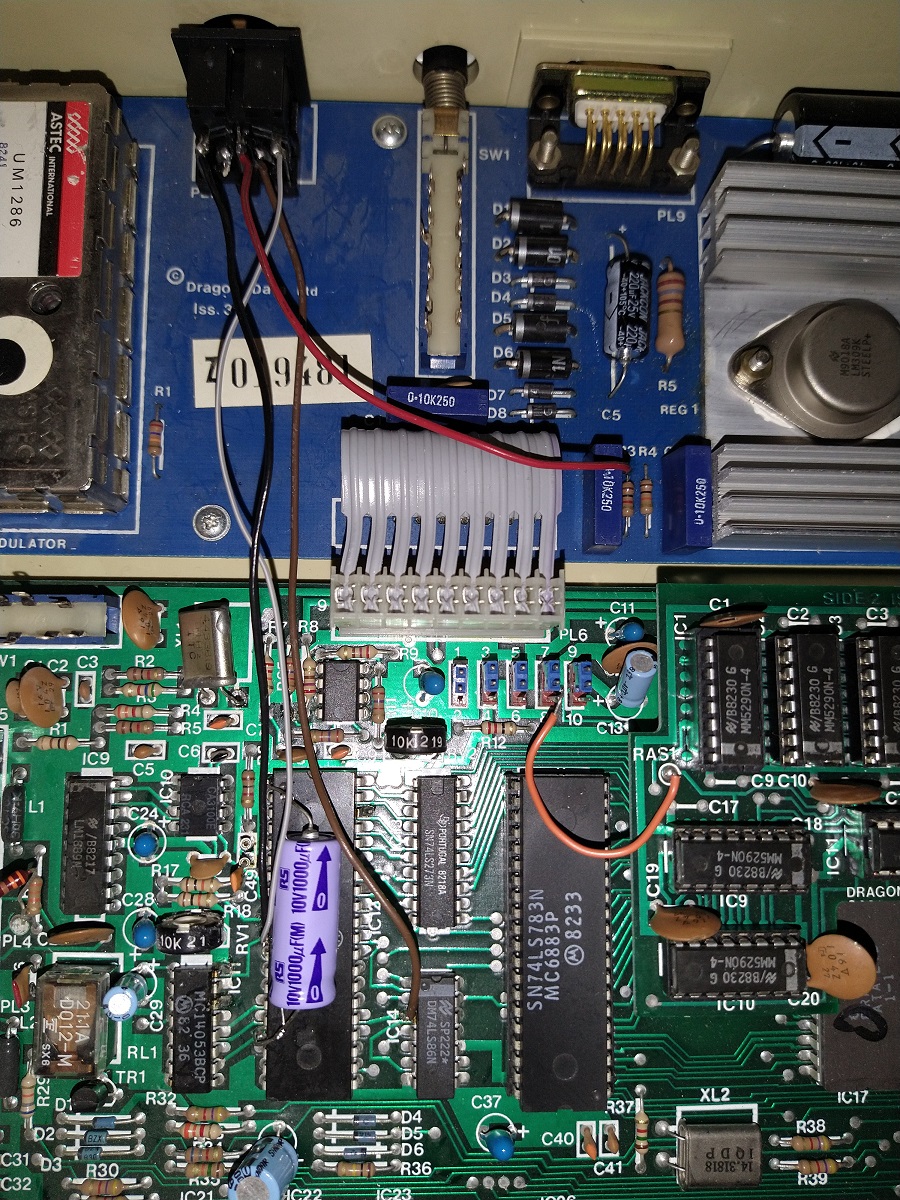
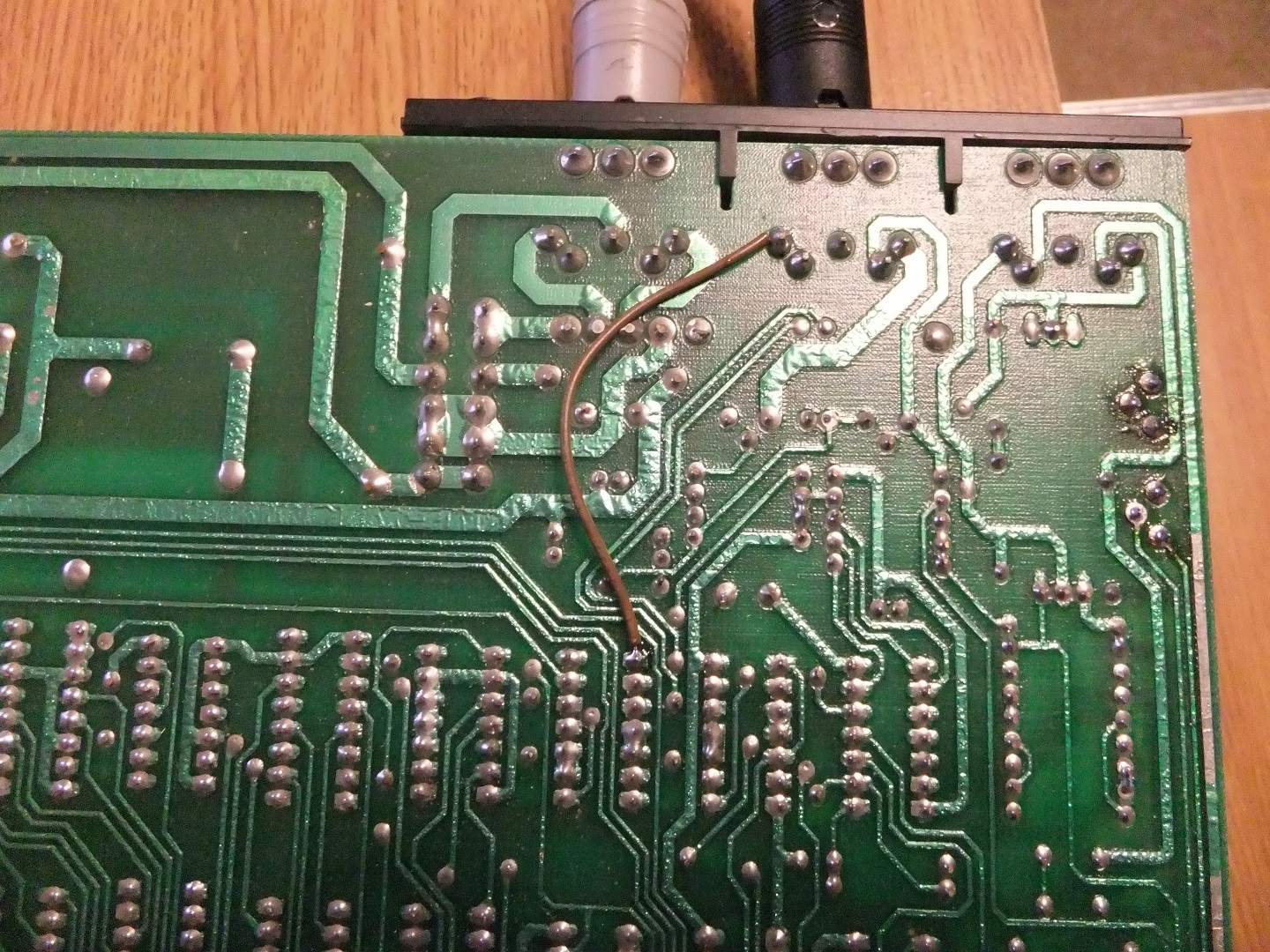
Dragon 32 (Analog YUV)
Modifications to create a Dragon external YUV video connector:
Remove the existing 3 pin (5 way) sound and video DIN socket from the power supply board.
Take a 270° 8 way pcb mounting DIN socket and cut off all the solder pins except those equivalent to the ones on the original DIN connector. I used this one:
https://uk.farnell.com/deltron-components/671-0801/din-audio-video-conn-jack-8pos/dp/2989969
Solder this in place of the original DIN on the power supply board.
Connect the following signals to the top of the DIN connector:
6847 Pin 10 (PB) to DIN pin 6
6847 Pin 11 (PA) to DIN pin 7
6847 Pin 17 (+5v) to DIN pin 8
IC14 (74LS86) Pin 3 (HSYNC) to DIN pin 5
Disconnect one end of R65 to disable the colour subcarrier and give mono video on the video output.
You can also disconnect one leg of the 4.43Mhz crystal to reduce noise
Your original composite cable can still be plugged in after this mod but you have to reconnect R65 and crystal to get composite colour
If you get 50Hz hum bars try connecting a 470uF to 1000uF capacitor across the 6847 power pins (Pin1 = GND, Pin 17= +5v)
You can now make up the following lead:
| RGBtoHDMI 6 way IDC | 8 way DIN | Notes |
|---|---|---|
| Pin 1 GND | Pin 2 | |
| Pin 2 HSYNC | Pin 5 | IC14 Pin 3 |
| Pin 3 U | Pin 6 | 6847 PIN 10 (PB) |
| Pin 4 Y | Pin 3 | Y |
| Pin 5 V | Pin 7 | 6847 PIN 11 (PA) |
| Pin 6 +5V | Pin 8 | Leave unconnected if powering Pi externally |
Pick up the sound from DIN pin 1 to feed to an external amplifier.
You will probably also have to adjust RV2 to set the DC level of the video output so that sync tips are at 0V (It won't lock if they are below 0V)
After connecting the the converter, adjust RV2 until you get a locked stable image.
Photo of modified Dragon 32: (This picked up +5v from R3 on the power board)
PAL Tandy color computer 1/2/MC10 (Analog YUV)
| RGBtoHDMI 6 way IDC | Internal Connections | Notes |
|---|---|---|
| Pin 1 GND | TCC1000 PIN 1 | |
| Pin 2 SYNC | TCC1000 PIN 17 | PAL HS |
| Pin 3 U | 6847 PIN 10 | PB |
| Pin 4 Y | TCC1000 PIN 6 | PAL Y |
| Pin 5 V | 6847 PIN 11 | PA |
| Pin 6 +5V | 6847 PIN 17 | Leave unconnected if powering Pi externally |
You will also have to pick up the sound internally via a 1K resistor to connect to an external amplifier
It is also recommended that you power the Pi zero externally for better noise immunity but if you are having issues, try both ways. Also powering externally results in instant video after the CoCo is power cycled.
NTSC Tandy color computer 1/2/MC10 (Analog YUV)
| RGBtoHDMI 6 way IDC | Internal Connections | Notes |
|---|---|---|
| Pin 1 GND | 6847 PIN 1 | |
| Pin 2 SYNC | 6847 PIN 38 | HS |
| Pin 3 U | 6847 PIN 10 | PB |
| Pin 4 Y | 6847 PIN 28 | Y |
| Pin 5 V | 6847 PIN 11 | PA |
| Pin 6 +5V | 6847 PIN 17 | Leave unconnected if powering Pi externally |
You will also have to pick up the sound internally via a 1K resistor to connect to an external amplifier
NOTE:
For the NTSC Color Computers you must also remove a capacitor (normally 150pf) on the Y output of the 6847 as it degrades the video signal and will result in a poor quality noisy image.
The component numbering varies depending on the issue of board you have. These are the ones found so far:
| Model | Model Number | Capacitor to cut |
|---|---|---|
| TRS-80 CoCo1 | 26-3002 | Not Fitted |
| TRS-80 CoCo2 | 26-3026 | C59 |
| TRS-80 CoCo2 | 26-3027 | C59 |
| TRS-80 CoCo2 | 26-3134 | C59 |
| TRS-80 CoCo2 | 26-3136 | C59 |
| TRS-80 CoCo2 | 26-3134A | C23 |
| MC-10 | 26-3011 | C33 |
It is also recommended that you power the Pi zero externally for better noise immunity but if you are having issues, try both ways. Also powering externally results in instant video after the CoCo is power cycled.
LumaCode / Apple II / ZX80 / ZX81 / UK101 / Nascom / Superboard II or any other mono computer
| RGBtoHDMI 6 way IDC | Phono Connector | Notes |
|---|---|---|
| Pin 1 GND | GND | |
| Pin 2 SYNC | VIDEO | Video on pins 2 & 4 |
| Pin 3 U | GND | |
| Pin 4 Y | VIDEO | |
| Pin 5 V | GND | |
| Pin 6 +5V | N/C |
Notes:
The ZX80/81 either require a composite video mod or the 220 ohm resistor mod which can be done as follows:
Open up the modulator and disconnect the wire going to the centre pin of the RF phono connector.
Then connect a 220 ohm resistor from the video input of the modulator to the centre of the phono connector.
You can then plug a phono cable into the modulator to feed the video to an RGBtoHDMI
Note this mod is only suitable for use with RGBtoHDMI as it will not have enough strength to drive a normal video input.
The PAL encoder on the PAL Apple IIe must be disabled (switch on motherboard) and artifact colour will only work with the manual SW2 switch. (NTSC Apples and PAL Apple II+ will auto detect colour modes)
TRS80 Model 1 (Mono) / Video Genie
| RGBtoHDMI 6 way IDC | 5 way DIN | Notes |
|---|---|---|
| Pin 1 GND | Pin 5 | |
| Pin 2 SYNC | Pin 3 | Picks up mod sync signal |
| Pin 3 U | Pin 5 | GND |
| Pin 4 Y | Pin 4 | Video |
| Pin 5 V | Pin 5 | GND |
| Pin 6 +5V | Pin 1 | Leave unconnected if powering Pi externally |
An unmodified TRS80 will work but you will have to use the auto calibrate occasionally because the composite sync signal is generated by resistor capacitor monostables which drift with temperature.
If you make the following modification, an alternative sync signal which is timed by the crystal can be output on an unused pin of the video connector and then the auto calibration should only need to be done once during initial setup.
Connect pin 1 (HDRV) of Z6 (74C04) to Pin 3 of the 5 way video DIN socket.
Use the "TRS_80" profile for an unmodified machine and "TRS_80_Modified" for one with the modification.
This modification can also be performed on the Video Genie with the HDRV signal being on pin 13 of IC1 in the Sync Gen (Untested)
Photo of mod on a 50Hz (PAL) TRS80 Model 1 Level II:
images/cables/trs80.jpg
Commodore 64 (with c0pperdragon's YUV interface)
| RGBtoHDMI 6 way IDC | 4 pole 3.5mm jack plug | Notes |
|---|---|---|
| Pin 1 GND | Body | |
| Pin 2 SYNC | Body (GND) | Sync is detected on Y |
| Pin 3 U | Ring next to Tip | B-Y |
| Pin 4 Y | Tip | Y |
| Pin 5 V | Ring next to Body | R-Y |
| Pin 6 +5V | N/C |
This will only work if c0pperdragon's YUV interface is fitted
See here:
https://github.com/c0pperdragon/C64-Video-Enhancement
Available here:
https://videogameperfection.com/products/commodore-component-video/
The latest 2.7 version of the firmware for c0pperdragon's board has support for RGBtoHDMI built in so if you can update the firmware yourself, you can skip reprogramming the palette below.
Latest 2.7 firmware is here (requires a USB Blaster programmer & software): https://github.com/c0pperdragon/C64-Video-Enhancement/releases
To enable support for RGBtoHDMI on the latest 2.7 firmware, after programming, put a link across pins 9 & 10 of the jtag connector (two pins closest to the back of the case). After that, putting the switch away from the YUV video connector outputs 288p with the special high contrast palette required by RGBtoHDMI so you should use it in that position. To output normal colours use one of the other two positions.
Before link fitted:
Switch towards YUV video connector = 288p
Switch in middle = 576p
Switch away from YUV video connector = 576p with scanlines
After fitting link on pins 9 & 10 on 2.7 firmware:
Switch towards YUV video connector = 288p
Switch in middle = 576p
Switch away from YUV video connector = 288p with high contrast palette for RGBtoHDMI
However it is likely that for the forseeable future the boards from video game perfection will still have older 2.6 firmware so you must follow the procedure below if you are unable to upgrade:
The 3 position switch on the interface should be set to 288p mode (towards the YUV video connector).
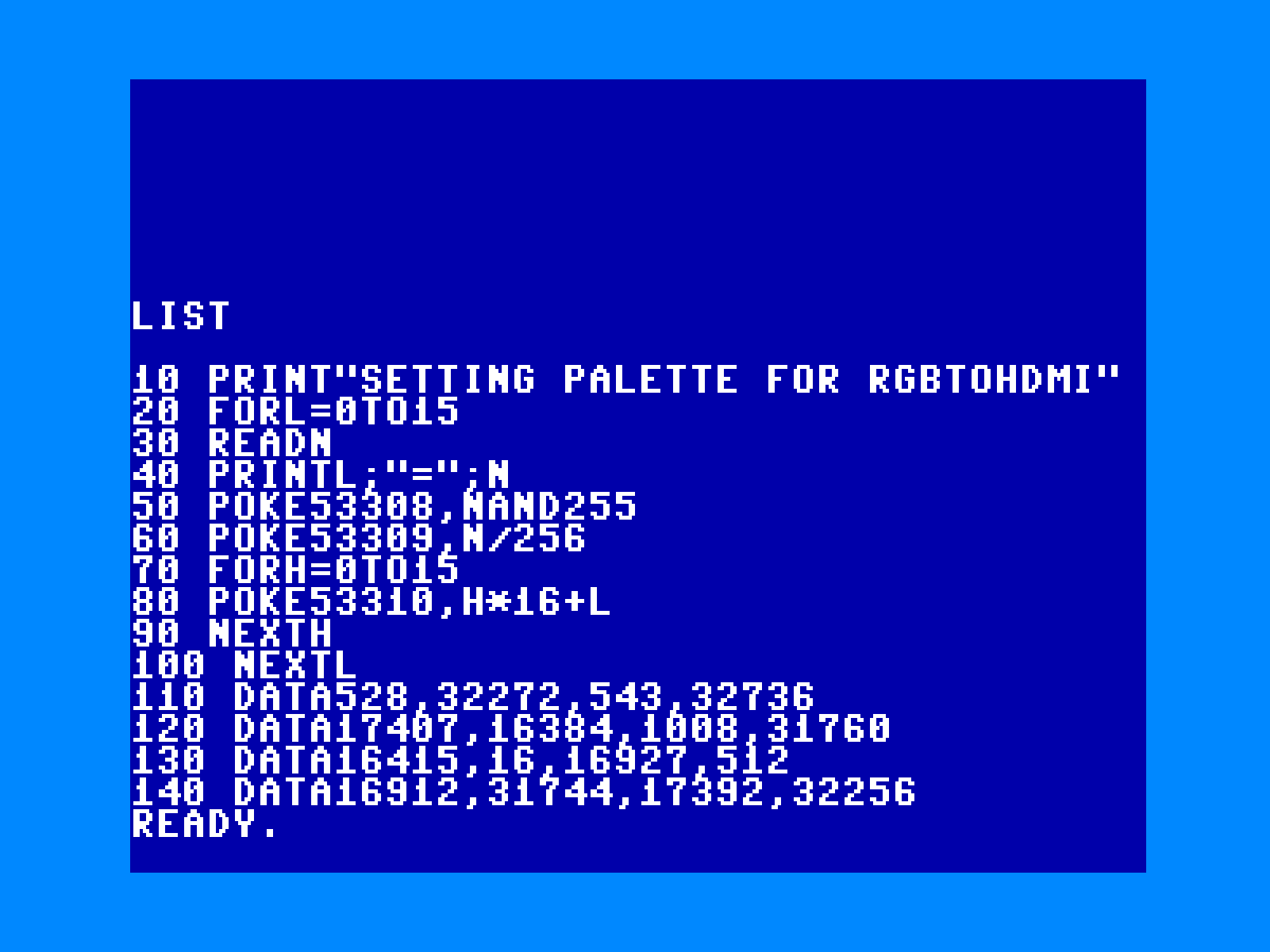
After fitting, you must reprogram the YUV interface palette to output a high contrast palette that RGBtoHDMI can discriminate to extract the raw digital pixel data.
This means the analog YUV output will not have 100% correct colours as they will be very saturated but the colours will be correct through RGBtoHDMI
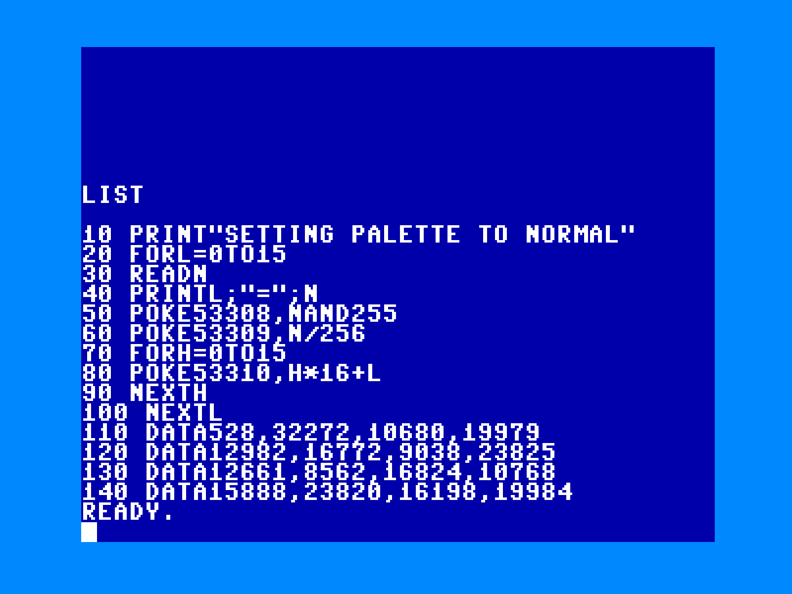
Type the following program into the Commodore 64:
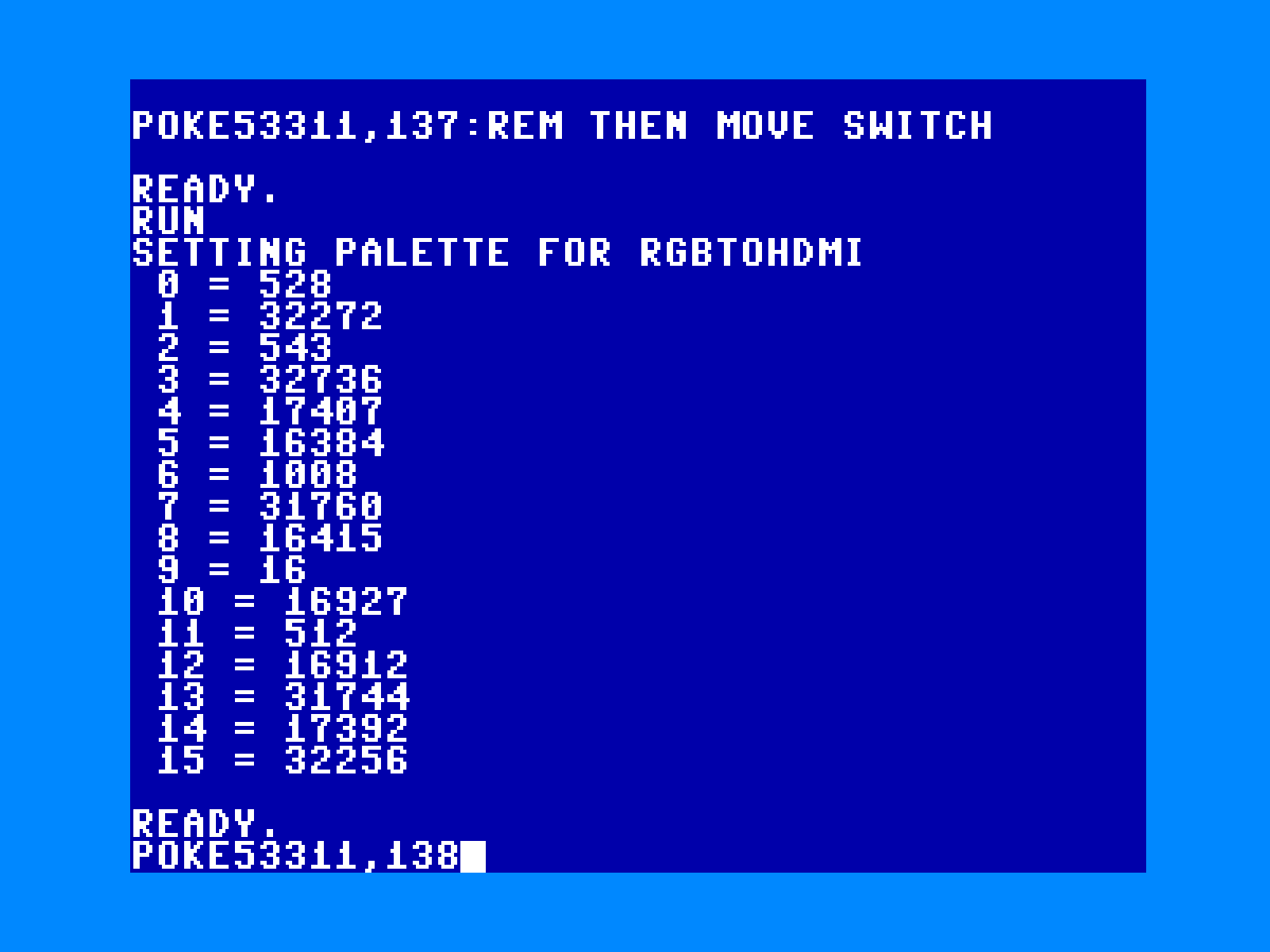
Then RUN it to confirm it outputs the same numbers as below:
(It won't have any effect at this stage)
Finally to reprogram type:
POKE 53311,137
Press Return
Move the interface switch to any other position and back again to signal you want to reprogram
Then type:
RUN
Press Return
Finally type:
POKE 53311,138
Press Return
The interface should now be reprogrammed with the right YUV levels for use with RGBtoHDMI
(This only needs to be done once, the values are saved in the interface)
To restore normal colours so the analog output can be used with an analog monitor, type in this program: