Wire Map New - ISS-Mimic/Mimic GitHub Wiki
Mimic Wire Map
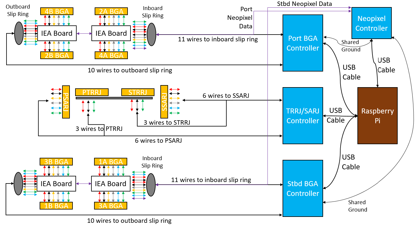
Mimic uses three microcontrollers to drive the 12 motors on the ISS model. Each of the 8 solar arrays are connected to the truss by a motor called the Beta Gimbal Assembly which turns the array to track the sun. The entire outboard truss (each side has 4 arrays attached) is rotated by a motor called the Solar Alpha Rotary Joint (SARJ). The inboard radiators rotate about a joint called the Thermal Radiator Rotary Joint (TRRJ).
A fourth microcontroller is used to control any LEDs on the model (used on the IEAs in our version).
All of the microcontrollers connect to a raspberry Pi which sends all the data they need to control the model.
In our project, we use DC motors for all of the BGAs and SARJs and servo motors for the TRRJs. Each DC motor requires 6 connections: motor +/-, encoder +/-, and encoder data 1/2. The servos require 3 connections: power, ground, signal.
We typically use custom made printed circuit boards (PCBs) to reduce the number of wires involved in the model, making it look cleaner and reduce bad/loose connections which can impact motor performance. Our circuit boards (Mimic HDMI Shield) plug directly on top of the microcontrollers and route each signal to an HDMI cable which terminates at a custom breakout board (Mimic HDMI Breakout) before the slip ring. After the slip ring, the wires are connected to another PCB called the Integrated Equipment Assembly (IEA) PCB (IEA PCB), which has places to solder LEDs to and a connector space for attaching the motors.
None of these PCBs are strictly required for the project, but they really help ease the construction process and reduce potential electrical problems. The zip files linked are gerber files, which can be uploaded to a PCB "fab shop" who will produce and ship the circuit boards. There are tons of fab shops available, the ones we use most frequently are All PCB, Seeedstudio, and Oshpark.
Regardless of using our custom PCBs, some motor shields will be required for all of the DC motors (one shield per microcontroller).
A basic overview of the wiring connections is shown below:
Wire Connection List
"inner" and "outer" motor pins refer to pin location on the motor shield, inner pins are nearer the center of the board.
Port BGA Controller
Inboard Slip Ring
2A
M2 pwr inner => 2A IEA PCB Pin 1 [motor power] (dark blue)
M2 pwr outer => 2A IEA PCB Pin 2 [motor power] (salmon)
3.3V => 2A IEA PCB Pin 3 [encoder power] (red)
Ground => 2A IEA PCB Pin 4 [encoder gnd] (black)
Pin D3 => 2A IEA PCB Pin 5 [encoder 1] (yellow)
Pin D2 => 2A IEA PCB Pin 6 [encoder 2] (gray)
4A PCB Pin 8 => 2A IEA PCB Pin 7 [neopixel data]
4A
M1 pwr inner => 4A IEA PCB Pin 1 [motor power] (dark blue)
M1 pwr outer => 4A IEA PCB Pin 2 [motor power] (salmon)
To reduce wires needed, both motor boards should share the same encoder power lines, so connect the IEA PCBs together at these pins:
2A PCB Pin 3 => 4A IEA PCB Pin 3 [encoder power] (red)
2A PCB Pin 4 => 4A IEA PCB Pin 4 [encoder gnd] (black)
Pin D1 => 4A IEA PCB Pin 5 [encoder 1] (purple)
Pin D0 => 4A IEA PCB Pin 6 [encoder 2] (green)
LED Data => 4A IEA PCB Pin 7 [neopixel data] (grey)
Outboard Slip Ring
4B
M3 pwr inner => 4B IEA PCB Pin 1 [motor power] (dark blue)
M3 pwr outer => 4B IEA PCB Pin 2 [motor power] (yellow)
3.3V => 4B IEA PCB Pin 3 [encoder power] (red)
Ground => 4B IEA PCB Pin 4 [encoder gnd] (black)
Pin D8 => 4B IEA PCB Pin 5 [encoder 1] (grey)
Pin D7 => 4B IEA PCB Pin 6 [encoder 2] (salmon)
2A PCB Pin 8 => 4B IEA PCB Pin 7 [neopixel data] (this will cross between the outboard and inboard IEAs)
2B
M4 pwr inner => 2B IEA PCB Pin 1 [motor power] (light blue)
M4 pwr outer => 2B IEA PCB Pin 2 [motor power] (orange)
To reduce wires needed, both motor boards should share the same encoder power lines, so connect the IEA PCBs together at these pins:
4B PCB Pin 3 => 2B IEA PCB Pin 3 [encoder power] (red)
4B PCB Pin 4 => 2B IEA PCB Pin 4 [encoder gnd] (black)
Pin D12 => 2B IEA PCB Pin 5 [encoder 1] (purple)
Pin D11 => 2B IEA PCB Pin 6 [encoder 2] (green)
4B PCB Pin 8 => 2B IEA PCB Pin 7 [neopixel data]
Stbd BGA Controller
Inboard Slip Ring
3A (previously labeled 1A)
M1 pwr inner => 1A IEA PCB Pin 1 [motor power] (light blue)
M1 pwr outer => 1A IEA PCB Pin 2 [motor power] (yellow)
3.3V => 1A IEA PCB Pin 3 [encoder power] (red)
Ground => 1A IEA PCB Pin 4 [encoder gnd] (black)
Pin D3 => 1A IEA PCB Pin 5 [encoder 1] (brown)
Pin D2 => 1A IEA PCB Pin 6 [encoder 2] (orange)
1A (previously labeled 3A) PCB Pin 8 => 3A (previously labeled 1A) IEA PCB Pin 7 [neopixel data]
3A Pin 8 (neopixel) => 3B IEA PCB Pin 7 (neopixel input). *** Note: Would prefer 3A Pin8 to 1B Pin 7, for cleaner wiring on the truss ***
1A (previously labeled 3A)
M2 pwr inner => 3A IEA PCB Pin 1 [motor power] (dark blue)
M2 pwr outer => 3A IEA PCB Pin 2 [motor power] (salmon)
To reduce wires needed, both motor boards should share the same encoder power lines, so connect the IEA PCBs together at these pins:
1A PCB Pin 3 => 3A IEA PCB Pin 3 [encoder power] (red)
1A PCB Pin 4 => 3A IEA PCB Pin 4 [encoder gnd] (black)
Pin D1 => 3A IEA PCB Pin 5 [encoder 1] (purple)
Pin D0 => 3A IEA PCB Pin 6 [encoder 2] (green)
LED Data => 3A IEA PCB Pin 7 [neopixel data] (grey)
Outboard Slip Ring
1B (previously labeled 3B)
M4 pwr inner => 1B IEA PCB Pin 1 [motor power] (dark blue)
M4 pwr outer => 1B IEA PCB Pin 2 [motor power] (yellow)
3.3V => 1B IEA PCB Pin 3 [encoder power] (red)
Ground => 1B IEA PCB Pin 4 [encoder gnd] (black)
Pin D8 => 1B IEA PCB Pin 5 [encoder 1] (grey)
Pin D7 => 1B IEA PCB Pin 6 [encoder 2] (salmon)
1A PCB Pin 8 => 1B IEA PCB Pin 7 [neopixel data] (this will cross between the outboard and inboard IEAs)
3B (previously labeled 1B)
M3 pwr inner => 3B IEA PCB Pin 1 [motor power] (light blue)
M3 pwr outer => 3B IEA PCB Pin 2 [motor power] (orange)
To reduce wires needed, both motor boards should share the same encoder power lines, so connect the IEA PCBs together at these pins:
3B PCB Pin 3 => 3B IEA PCB Pin 3 [encoder power] (red)
3B PCB Pin 4 => 3B IEA PCB Pin 4 [encoder gnd] (black)
Pin D12 => 3B IEA PCB Pin 5 [encoder 1] (purple)
Pin D11 => 3B IEA PCB Pin 6 [encoder 2] (green)
1B PCB Pin 8 => 3B IEA PCB Pin 7 [neopixel data]
SARJ/TRRJ Controller
PSARJ
M1 pwr inner => [motor power]
M1 pwr outer => [motor power]
3.3V => [encoder power]
Ground => [encoder gnd]
Pin D3 => [encoder 1]
Pin D2 => [encoder 2]
SSARJ
M2 pwr inner => [motor power]
M2 pwr outer => [motor power]
3.3V => [encoder power]
Ground => [encoder gnd]
Pin D8 => [encoder 1]
Pin D7 => [encoder 2]
PTRRJ
5V => [motor power]
Ground => [motor power]
D9 => [motor data]
STRRJ
5V => [motor power]
Ground => [motor power]
D10 => [motor data]
Neopixel Controller
Since the circuits are connected to each, we need to make sure they are all at the same ground voltage potential, so connect ground pins between the Port BGA, Stbd BGA, and Neopixel Controllers.
Ground => Port BGA Controller Ground
Ground => Stbd BGA Controller Ground
Now for the neopixel data:
Neopixel 1 => Port BGA Controller Neopixel Input Pin (if using our shield, otherwise Pin 7 on the IEA PCB)
Neopixel 2 => Stbd BGA Controller Neopixel Input Pin (if using our shield, otherwise Pin 7 on the IEA PCB)