Lab 5 1: Routing Lab - Hsanokklis/2022-2023-Tech-journal GitHub Wiki
Objective: Configure and observe a simple routed network.
Goals:
- Configure a network
- Observe the Layer 2 header changes as a packet crosses a router
- Recognize the role of the default gateway
Part 1: Building the Network
1. Connect the network:
Use the Router-PT-Empty. You will need to add three PT-ROUTER-NM-1CFE Modules to the router
- Go to the physical tab of the router

- Turn off router

- Drag 3 PT-Router-NM-1CFE modules to the rightmost slots in the router


- Connect the devices on your network
IF THE SWITCH SAYS EMPTY IT WILL NOT HAVE ETHERNET PORTS TO CONNECT TO (use Switch-PT not empty or add ethernet ports)
-
PC HELLO!(FastEthernet0) --> Switch0(FastEthernet0/1)
-
PC1(FastEthernet0) --> Swicth0(FastEthernet1/1)
-
PC2(FastEthernet0) --> Swicth0(FastEthernet2/1)
-
PC3(FastEthernet0) --> RouterPT(FastEthernet0/0)
-
PC Ping Me(FastEthernet0) --> RouterPT(FastEthernet1/0)
-
SwitchPT(FastEthernet3/1) --> RouterPT(FastEthernet2/0)
YOU SHOULD USE A COPPER-CROSS OVER CABLE WHEN CONNECTING DEVICES ON THE SAME OSI LAYER(HUB-HUB, PC-PC, PC-ROUTER, PC-PRINTER).
COPPER STRAIGHT-THROUGH WIRES ARE USED TO CONNECTED DEVICES OPERATEING AT DIFFERNT OSI LEVELS(HUB-ROUTER, SWITCH-PC)

3. Configure the IPs on the router interfaces. You will need 3 different network/IPs
- FastEthernet0/0(PC3)

- FastEthernet1/0(Ping Me)
- FastEthernet2/0(Switch0)

THESE THREE IPS WILL BE USED AT THE DEFAULT GATEWAY IP ADDRESSES SINCE YOU ARE TECHNICALLY CONNECTING 3 LANS
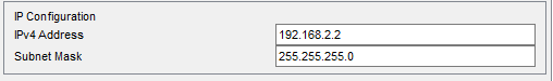
4. Set the appropriate IP's to your workstation's. Workstations IP should be in same network as default gateway.
IP addresses for the PCs
- Ping Me(Ethernet1/0)


- PC3 (FastEthernet0/0)


- PC HELLO!


- PC1


- PC2


5.Once all of the interfaces are configured, try pinging from HELLO! laptop to Ping Me laptop
successful ping from HELLO!(192.168.3.30) to Ping Me(192.168.2.10)

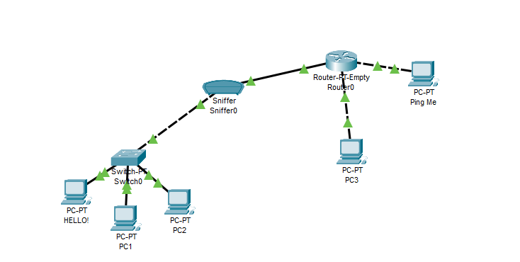
Diagram of Understanding:

the router is connecting LANs, the switch is connecting the PCs
Part 2: Packet Capture Observation
- Install a Sniffer between the switch and the router
- Go to end devices and drag the sniffer onto the screen

- Connect the switch and the router to the sniffer
I had to use the copper cross over wire to connect the switch to the sniffer
2. Using the sniffer inspect packets going from HELLO! to Ping Me and back. Ping both ways


3. Replace switch with a hub and repeat above steps

- GUI with hub

What was different about the sniffer information when it was connected to a hub?
The hub sniffer GUI only displayed the ARP and ping packets that were broadcasted. The switch sniffer GUI had a lot more packets that were travelling such as STP and DTP.