Electronics Hardware - HenriquesLab/NanoJ-Fluidics GitHub Wiki
Metal surfaces
Please keep the controllers off metal surfaces!
One thing that must be kept in mind is that the Arduino controllers have unprotected connections at the bottom. If they are placed on top of a metal surface, this will short circuit some connections and the controller won't work. We haven't seen lasting damage occurring, but the controller won't do it's job while it's on the surface and until it's been reset.
Resetting after it doesn't start on a metal surface
If you realize your controller isn't responding because it was left on a metal surface, unplug all connections and remove it from the table. Wait at least 30 seconds (to release any charge in capacitors) and try again to reconnect to it.
Installing the shields
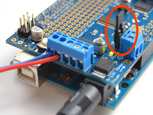
In our configuration, we are powering the Arduino, shields and Lego motors using a single power supply. To do this, each shield must have the Power Jumper set. A jumper comes with each shield and must be set as shown in the below picture:
Soldering headers on the shields
Next, the shield headers (the pins that allow the shield to be installed on to the Arduino) need to be soldered. If only one shield will be used, then the shield headers that come with the shield should be sufficient. If more than one shield will be used, then the stacking headers (bought separately) should be used. Either task is simple and both are described in the Adafruit website quite succintly.
Installing cables on the shields
Each shield can control up to 4 pumps. There are 4 possible motor connections (M1-M4). Connectors M1 and M2 are on one side of the shield and connectors M3 and M4 are on the opposite side. These are marked directly on the shield as is visible on the image below. The image also shows the positive and negative leads on the connectors (there is an extra ground (gnd) connector, which is not used).

To connect each shield to a pump, we first take two female-female jumper wires and cut them in half. Then, using a small Phillips head screwdriver, fit one half of the wire to one of the connection ports on the motor shield.

Installing cables on the pumps
The ribbon connector that comes with the lego pumps will have to be cut and wired properly to allow the pumps to be controlled with the arduino controller. The ribon cables are also a bit short and composed of lots of small thin cores, making them hard to connect to the arduino shields. We solder longer cables to these ends, making it easy to connect to the Arduino. This process is shown in the figure below.
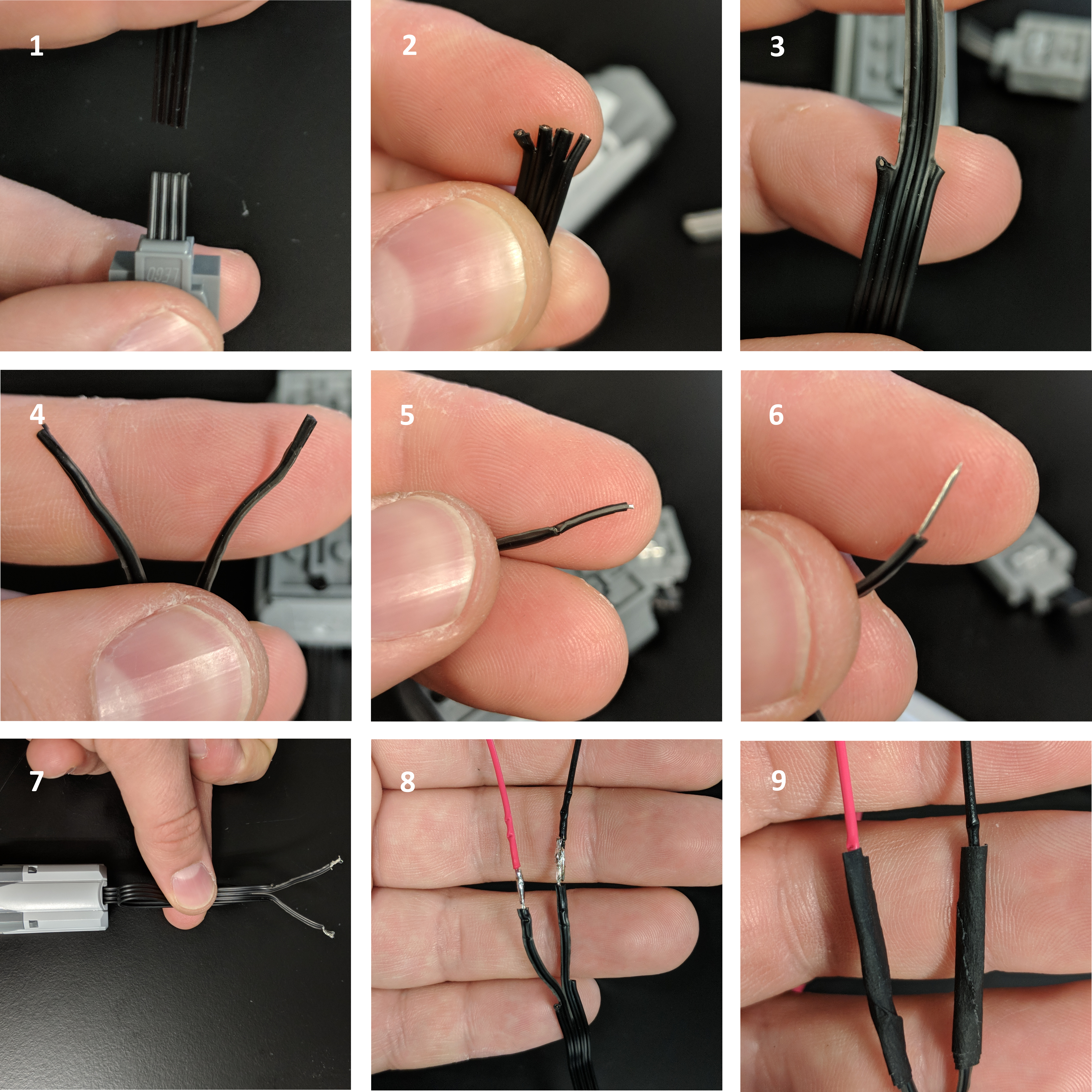
- First, cut the Lego connector at the end of the ribbon cable.
- The ribbon cable consists of 4 smaller cables. Separate the ends of the cable from one another using a cutting device (like a pair of scissors).
- The two outer cables are unused by us so we peel them and cut them out.
- Peel the two middle cables away from each other.
- Strip the ends of the cables. This is easy to do by first knicking the ends with a cutting device (like, say, the scissors mentioned above).
- The plastic then just be pulled away.
- It's important to figure out which cable is which. The cable at the top of this sub-figure is the positive lead and the bottom is the neutral lead.
- Solder a single-core cable to each lead. We use the UK colour system where the red is positive and black is neutral.
- Finally, cover the cables so they don't touch and short circuit each other. This is easily done with tape as shown, but heatshrink wrap will give it a more polished look.
You can now connect the positive and negative lead of the pump to the respective connectors on the motors shield, as explained in the previous section.
Installing peristaltic pumps
This process is simple and described in the peristaltic pump page.
Shield stacking
When using multiple shields, one final soldering step is required. As explained in the Adafruit website, each should must have an address and this is set by soldering it into the shield. For the shields to work with the NanoJ-Fluidics software, each shield must be numbered sequentially, starting from 0. So, if 3 shields are required, one shield will be shield 0, another will be shield 1 and the final one will be shield 2. The shields can be stacked in any order, regardless of its address but we prefer to place first shield 0, then shield 1 then shield 2, and so on, which facilitates identification.
Software
You may now proceed to the firmware installation portion of the wiki.