04 Board Pins & Wiring - HefnySco/OBAL GitHub Wiki
Board Pins & Wiring
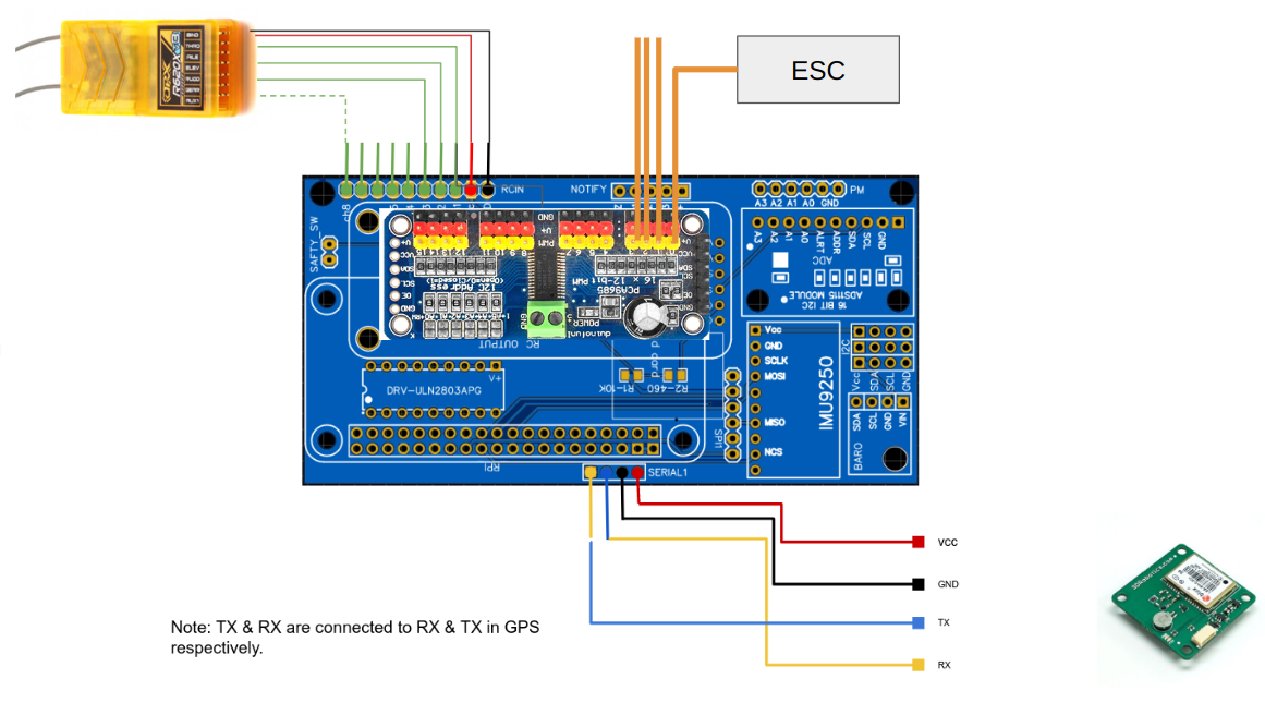
Wiring Receiver & GPS
OBAL supports both PWM & PPM receivers. The are connected the same. The difference is in the code. You need to enable PPM from the code in source code.
Important Notice: For GPS notice you should connect TX of the board to RX of the GPS & vice versa.
Safety Switch
Please connect SAFETY_EN to an on/off switch. It will disable motors by blocking PWM signals to ESC. Even if ardupilot code arms motors, they will not spin as there is no signal reaches the motors when button if off. The SMD resistors also ensures that the motors turns off if RPI restarted accidently while motors are spinning.
Powering the Board
The board has two separate power lines:
- (VCC) +5V for Raspberry-PI & the sensors. [any vcc pin and the +5v on raspberry-pi pins]
- (V+) +5V for leds, buzzer and servos. [V+ pin next to leds, V+ pin on PCA9685, and the red column pins on PCA9685]
You can use a single power source for both of them if you add a jumper between the V+ & the VCC pins in the PCA9685 breakout.
I recommend powering them separately. You can use the 5V & Gnd Pin of RPI for power the board via a 5VBEC 2-3AMPs based on the RPI model you are using. And you can use another BEC or the ECS BEC by connecting them to the red raw of PCA9685 and power leds, buzzer and servo. This is a safer way.
It is not recommended to fly using the micro USB socket for power supply, apart from the drawbacks of the micro USB connector itself, on the Pi1/2/3 (as well as Pi1A+ and Pi3A+) there is a polyfuse in the current-path which lowers voltage and limits current which can lead to brownouts and instabilitues.
