6.VIRTUAL IMPLEMENTATION - H-Division-2021-2022-Even/Repo-14 GitHub Wiki
| Sl.No. | Subsystem Name | Components | Name |
|---|---|---|---|
| 1. | User-Interface Unit | IR Sensor | Tejas |
| Bluetooth Module | |||
| Push Buttons | |||
| Arduino Board | |||
| Jack | |||
| 2. | Shape Display Unit Part 1 | Stepper Motor | Vighnesh |
| Outer disk | |||
| Rod to support stepper motor | |||
| Casing of Shape Displaying Unit | |||
| 3. | Shape Display Unit Part 2 | DC Motor | Anushika |
| Inner Rod | |||
| Rod to support DC motor | |||
| Combined 2-Relay Module | |||
| Pointer | |||
| Colour Sensor | |||
| 4. | Indication Unit | Buzzer | Annapurna |
| LED | |||
| Bread Board | |||
| Casing of Indication and User Interface Unit |
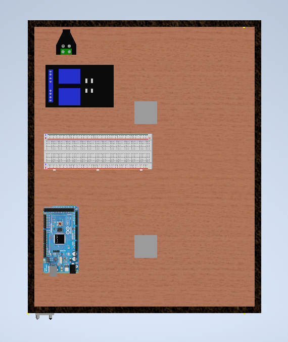
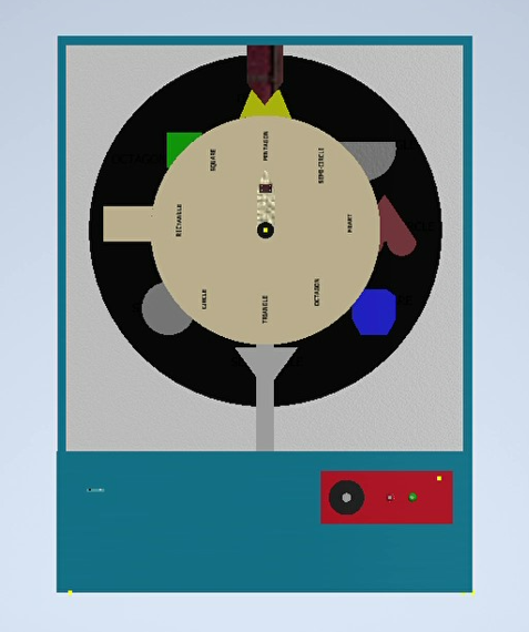
TOP VIEW
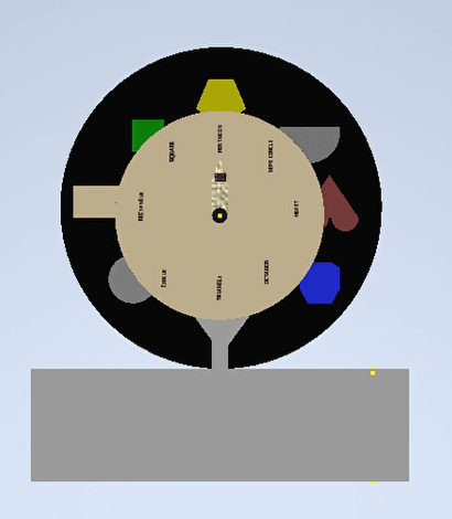
Front view:
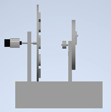
Side view:
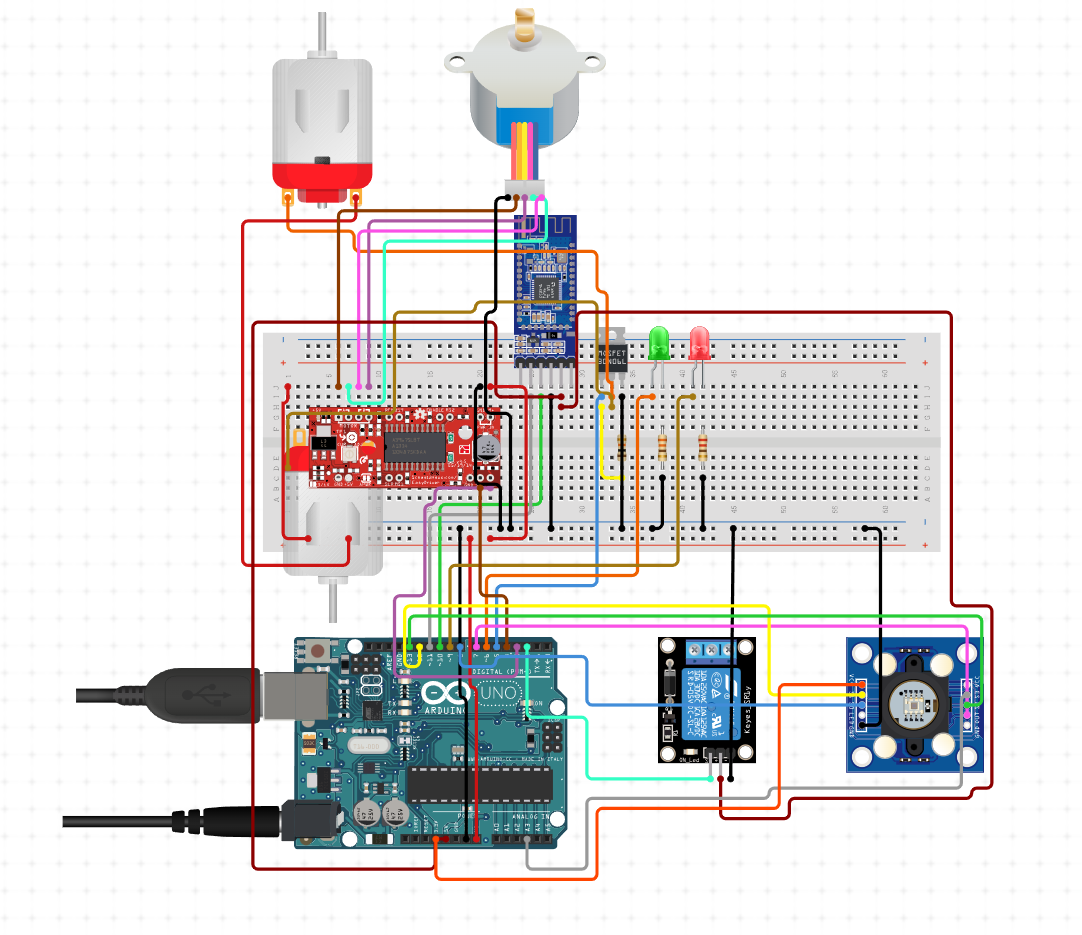
- Step 01 - Start.
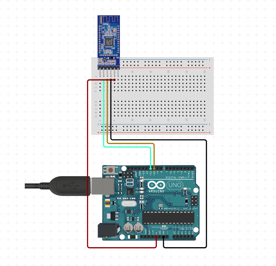
- Step 02 - Activate the bluetooth module.
- Step 03 - Provide the options to the user. if the data pressed by the user is '1'- ON the DC Motor. else if data pressed by the user is '0' - OFF the DC motor. else if data passed by the user is '2' - Activate the stepper motor else if data passed by the user is '3' - LED blink
- Step 04 - Send the signals to the shape displaying unit according to the data passed.
- Step 05 - Stop.
-
Step 01 - Start.
-
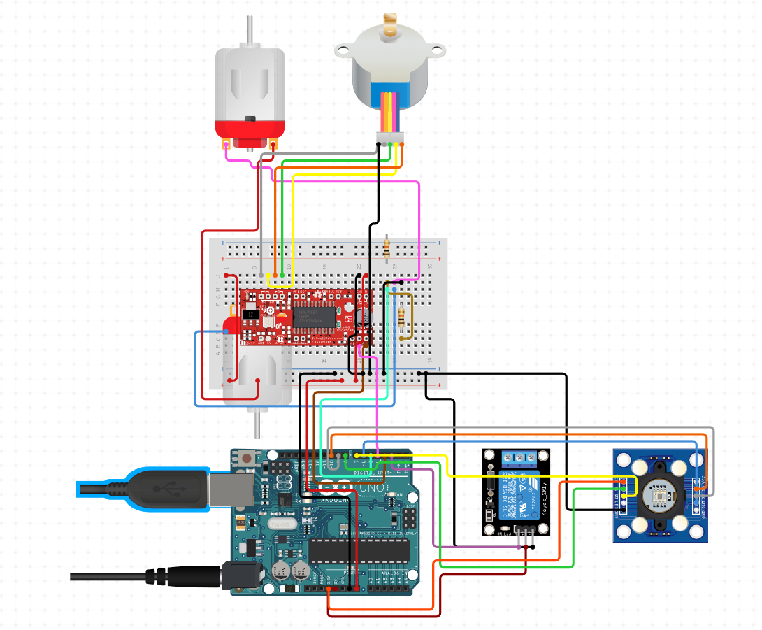
Step 02 - if the data passed is '1' - ON the DC motor and start rotating the outer disk.
else if the data passed is '0' - OFF the DC motor and also sense the colour on which the shape lands. Store the value of colour in a variable. else if data passed is '2' - Activate the stepper motor such that everytime the data passed is 2 , the pointer of the inner disk moves by a specified angle. Also increment the count value by 1. else if data passed is '3' - Off the stepper motor and check the values of colour and count. -
Step 03- if colour==count Green LED blinks.
else Red LED blinks. -
Step 04- Activate the stepper motor after a delay of 5 seconds and return the pointer of the inner disk back to its original position.
-
Step 05- Stop.
-
Step 01 - Start.
-
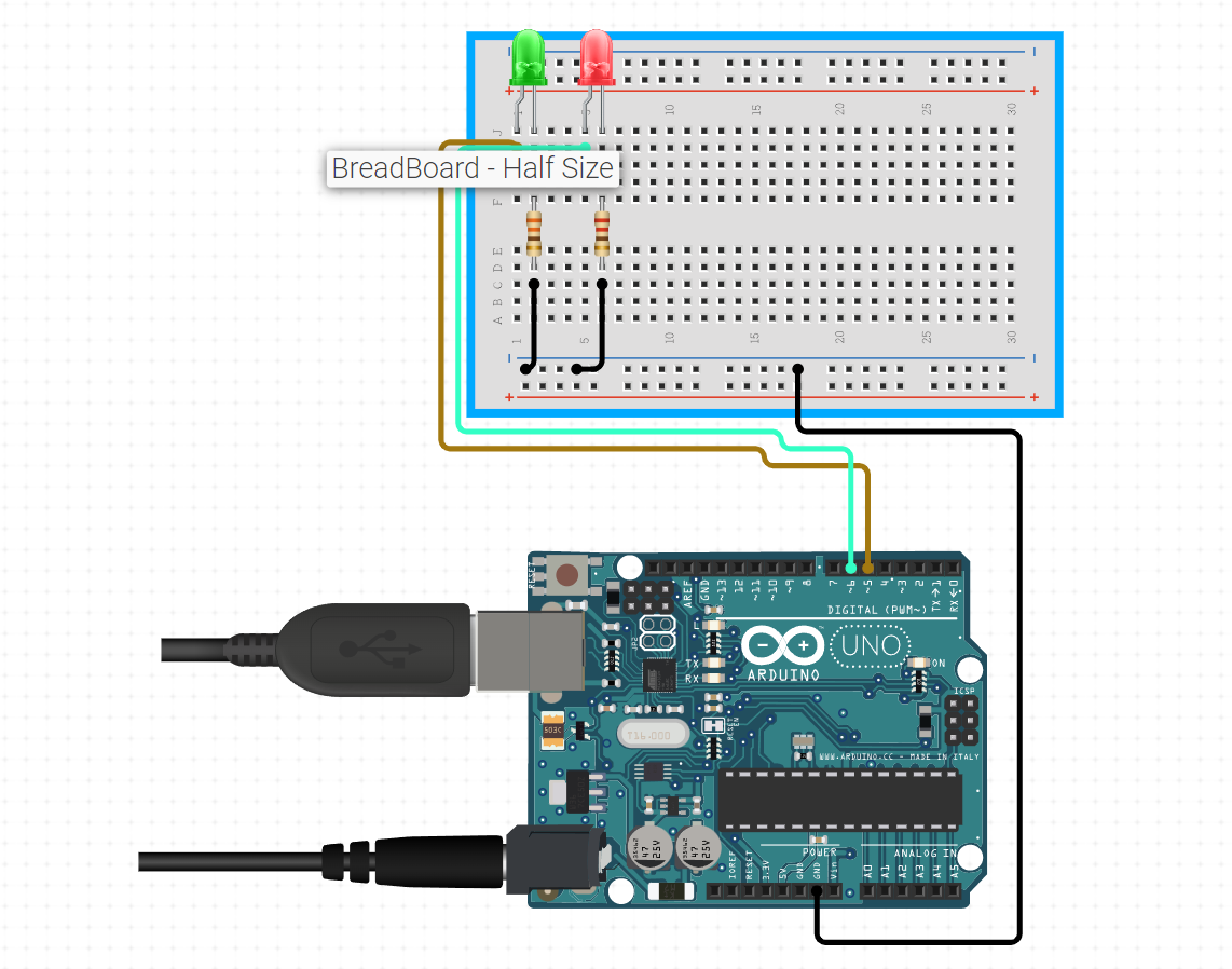
Step 02 - if the colour==count Blink green LED indicating it to the user that the answer is correct
else Blink the Red LED indicating it to the user that the answer is wrong. -
Step 04 - Stop.
-
Step 01 - Start.
-
Step 02 - Activate the bluetooth module.
-
Step 03 - Provide the options to the user. if the data pressed by the user is '1'- ON the DC Motor. else if data pressed by the user is '0' - OFF the DC motor. else if data passed by the user is '2' - Activate the stepper motor else if data passed by the user is '3' - LED blink
-
Step 04 - Send the signals to the shape displaying unit according to the data passed. if the data passed is '1' - ON the DC motor and start rotating the outer disk.
else if the data passed is '0' - OFF the DC motor and also sense the colour on which the shape lands. Store the value of colour in a variable. else if data passed is '2' - Activate the stepper motor such that everytime the data passed is 2 , the pointer of the inner disk moves by a specified angle. Also increment the count value by 1. else if data passed is '3' - Off the stepper motor and check the values of colour and count. -
Step 05- if colour==count Green LED blinks.
else Red LED blinks. -
Step 06- Activate the stepper motor after a delay of 5 seconds and return the pointer of the inner disk back to its original position.
-
Step 07- Stop.
| S.no | Name of the parts | Description | Quantity | Cost |
|---|---|---|---|---|
| 1 | DC Motor | 60 RPM | 1 | 130.00 |
| 2 | Jack | -- | --- | 1 |
| 3 | Jumper Wires Pack | M/M & M/F | 1 | 65.00 |
| 4 | Aluminium Channel | -- | 1 | -- |
| 5 | Bluetooth module | -- | 1 | 150 |
| 6 | Acrylic Sheet | -- | 1 | -- |
| 7 | Nylon Rod | -- | 1 | -- |
| 8 | L-Clamps | -- | 4 | -- |
| 9 | Nuts & Bolts | -- | 4 | -- |
| S.no | Name of the parts | Description | Quantity | Cost |
|---|---|---|---|---|
| 1 | Aluminium Channel | -- | 1 | -- |
| 2 | Arduino | Mega 2560 | 1 | 1566.00 |
| 3 | Stepper Motor | - | 1 | 75 |
| 4 | Acrylic Disc | -- | 1 | -- |
| 5 | Jumper Wires Pack | M/M & M/F | 1 | 65.00 |
| 6 | Arduino cable | -- | -- | 51.00 |
| 7 | Gears | -- | -- | -- |
| 8 | Nuts & Bolts | -- | 20 | -- |
| 9 | Foam Sheet | -- | 1 | -- |
| S.no | Name of the parts | Description | Quantity | Cost |
|---|---|---|---|---|
| 1 | Arduino | Mega 2560 | 1 | 1566.00 |
| 2 | LED's | Green and Red | 2 | 10.00 |
| 3 | Jumper Wires Pack | M/M & M/F | 1 | 65.00 |
| 4 | Color Sensor | TCS230 | 1 | 280.00 |
| 5 | Foam Sheet | -- | 1 | -- |
| 6 | Breadboard | -- | 1 | -- |
| 7 | Hinges | -- | 8 | -- |
| 8 | Nuts & Bolts | -- | 32 | -- |
| Sl.no | Name of the parts | Description | Quantity | Cost |
|---|---|---|---|---|
| 1 | Adaptor | 5V | 1 | 405 |
| 2 | Stepper Motor | - | 1 | 75 |
| 3 | DC Motor | 1 | 130.00 | |
| 4 | Relay module | --- | 1 | 50 |
| 5 | Arduino | Mega 2560 | 1 | 1566.00 |
| 6 | Jack | -- | 3 | |
| 7 | LED's | -- | 2 | 10 |
| 8 | Jumper Wires Pack | M/M | 1 | 65 |
| 9 | Jumper Wires Pack | M/F | 1 | 65 |
| 10 | L Clamp | - | 2 | 50 |
| 11 | Aluminium Channel | - | 1 | 125 |
| 12 | Color Sensor | TCS230 | 1 | 175 |
| 13 | Gears | -- | -- | 110 |
| 14 | Breadboard | -- | 1 | -- |
| 15 | Hinges | -- | 8 | -- |
| 16 | Nuts & Bolts | -- | 56 | -- |