Simulate_the_physics_of_bicycle_ride - GoldenCheetah/GoldenCheetah GitHub Wiki
Exploiting the trainer capabilities to simulate the physics of a bicycle ride
Many stationary exercise bicycles have a simple adjustment knob to vary the resistance. On those trainers, it is not possible to command the resistance by software, and the resulting cadence, speed and power output may or not be available. Smart trainer exercice bicycles allow to vary the resistance, and measure the speed and power output, by software. It is then possible to simulate a bicycle ride, like riding up Mont Ventoux.
To simulate a bicycle ride, a workout file describes the altitude, as a function of the distance on the road, from which the slope (gradient) can be computed at any point along the road. The GPS coordinates of a ride can serve the same purpose, providing not only the altitude along the road but also the latitude and longitude. Those can be used to display the position on a map. This may be coupled with a video (Media) of the road, and a Video Sync file telling the correspondance between the road distance and video frame. It is then possible to offer an interesting simulation of a bicycle ride, both in terms of effort and visuals.
Some smart trainers receive as input all the relevant parameters (total rider weight with bicycle m, Slope sl, wind resistance cd_a_rho, head wind speed w, and rolling resistance c_rr). They measure the speed v, as well as the cadence, power and other parameters, and accordingly apply the corresponding resistance on the bicycle wheel. This is the case for several recent models, through extensions to the ANT+ FE-C Fitness Equipment Control profile, and the Bluetooth 4.0 FTMS Fitness Machine service. GoldenCheetah supports the Wahoo Kickr, Tacx Vortex, and Kurt Kinetic. Under ANT+, the weight parameter appears not yet passed to the device, and thus a default value is currently used.
Other trainers simply allow to specify a resistance. This is the case for the Tacx Fortius and Tacx Imagic. The software can compute the resistance from the relevant parameters (total rider weight, slope, wind resistance, head wind speed and rolling resistance). Since GoldenCheetah has full control over this computation, this allows even more freedom to make refinements or adjustments.
Some trainers allow to specify the slope, instead of the resistance. This is the case for the Computrainer and the Monark LC Novo. It is more problematic, since the Rider weight, an important factor, is not taken into account for those, at least in GoldenCheetah. If the default parameters are known, it is possible to compute a modified slope, to account for the difference between the default values and the actual values for the Rider weight, or for other factors like the Wind resistance.
Finally, while pretty much all smart trainers offer a target power mode, the remaining training devices only offer that mode. This is the case for the Daum, ErgoFit, Kettler, KettlerRacer, and other Monark models in GoldenCheetah. However, it is possible to compute the resistance associated to a given power, and thus to achieve a slope simulation, with proper software support. This will be discussed later. However, depending on the hardware, because of the communication delays involved, implementing the feedback loop in the computer, for slope simulation, may not be as affective as within the trainer. In control theory, delays in the feedback loop can cause many problems, like oscillation.
Modeling the resistance
The numerical modeling of riding a bicycle is nicely explained in betterbicycles.org [1] but a more thorough reference is the book Bicycling Science [2]. The force exerted by the cyclist on the pedals f_p has mostly to overcome the resistance in the mechanical losses, the air resistance f_a, the slope f_s (gravity), the rolling resistance f_r and the average bump resistance f_b. The difference between the force exerted by the cyclist and the resistance, f_acc, will cause acceleration a and increase (decrease) the speed of the rider. The mass m of the rider and bicycle accelerates by a, but additional inertia is caused by the wheels (and cranks) accelerated rotation. To account for the total inertia, the rider equivalent mass, m_e, takes into account the wheels moment of inertia. We assume here a reasonably smooth road and neglect the bump resistance, f_b. Similarly, we assume that the force and power is measured at the rear wheel and we do not account for mechanical losses in the chain.
f_p - (f_a + f_s + f_r) = f_acc = m_e * a
f_p = Fp(m, m_e, a, v, sl, cd_a_rho, w, c_rr) = f_a + f_s + f_r + m_e * a
Air resistance
The air resistance is the main factor at high speed and depends on the square of the speed of the air, relative to the rider, and the rider wind resistance cd_a_rho. In fact, cd_a_rho can be further expressed in terms of the rider drag resistance cd, frontal area A, and the air density rho. The relative speed is the head wind speed w plus the rider speed v. The absolute value is taken once, to obtain the square of the relative speed, while keeping the force direction. Indeed, if the headwind is negative and larger than the rider speed, the relative speed will be negative and the resistance force will be negative, i.e. pushing the rider.
f_a = Fa(v, cd_a_rho, w) = 1/2 cd_a_rho (v + W) * abs(v + W)
cd_a_rho = cd * A * rho
The air density itself varies with the altitude [3]. With pb the pressure at sea level (101325 Pa), tb the temperature at sea level (288.15 K), lb the temperature lapse rate (0.0065 K/m), h the altitude, g0 the sea level gravitatinal acceleration (9.80665 m/s²), m_air the molar mass of air (0.0289654 kg/mol), and r_star the universal gas constant (8.31447 J/(mol·K)), the density can be computed as a function of the altitude, to account for a lower air pressure when a rider climbs a mountain.
rho = pb * m_air / (r_star * tb) * pow((1 - lb * h / tb), (g0 * m_air) / (r_star * lb))
Slope resistance
The slope resistance is a major factor affecting everyone riding in the mountains, fast or slow rider. It is a direct effect of the gravitational acceleration g on the rider mass m, along the direction of movement defined by the slope sl. The slope is generally expressed as a ratio of the rise (vertical change) over the run (horizontal change), often as a percentage. A road with a 45 degrees angle would represent a slope of 100% (rise / run = 1). The projection of the gravitational force along the road is given by the ratio of the rise over the slope length.
sl = slope_percentage / 100
run = 1, rise = sl, slope_length = sqrt(1 * 1 + sl * sl)
f_s = Fs(m, sl) = m * g * sl / sqrt(1 * 1 + sl * sl)
Often, a simpler approximation of this equation will be used, using simply sl instead of dividing it by sqrt(1 + sl^2). For a slope of 1%, the difference is 1 : 1.00005, for 10% it is 1 : 1.005, and for 20% the difference is 1 : 1.02.
f_s = m * g * sl
Rolling resistance
The rolling resistance is proportional to the gravitational force perpendicular to the road, and the rolling resistance coefficient c_rr. The projection of the gravitational force perpendicular the road is given by the ratio of the run over the slope length.
f_r = Fr(m, c_rr, sl) = m * g * c_rr * 1 / slope_length
Simulating a ride on a trainer
On a trainer, there is some inertia associated with the moving parts: crankset, chain, rear wheel, and roller for older models, or flywheel for newer direct drive models. This offsets to a certain extent the need to model the rider inertia and should be substracted from the resistance needed from the trainer brake, f_brake. The equivalent mass for this inertia, drive train and flywheel is m_f.
f_brake = f_p - m_f * a
Trainer and drive train inertia
On a trainer with the rear wheel in contact with a small roller, like the Fortius, the inertia is quite negligible. However, this trainer does model the inertia internally. Indeed, in TotalReverse [4], the authors document that one field in the Fortius T1941 brake motor control command specifies the "weight of rider+bike in kg for realistic simulation of riders mass; this simulates kinetic mass and not gravitational mass". While the rider inertia (kinetic mass), m_e * a, can be included in the braking force to apply, it is advantageous to simulate it directly in the trainer. Indeed, the force due to the inertia varies very quickly (derivative of the speed) and is thus better simulated internally to the trainer, with a tight low-latency feedback loop. Tests on the Fortius with 0 gradient, no rolling resistance and no drag resistance, comparing the acceleration time when specifying a 10kg rider and a 110kg rider, show a clear difference. The latter is much slower, because of the inertia simulated by the trainer.
Many newer trainers use a direct drive. The rear wheel is removed and the chain rotates a cassette installed on the trainer flywheel. This avoids any tire slippage, and also reduces the noise and vibrations due to the contact with the roller. Different models advertise heavy flywheels as a strong point. For example, the Wahoo Kickr Core has a 5.4kg flywheel. The moment of inertia is denoted i_fly, for a flywheel where the mass m_fly is concentrated in a thin ring of radius r_fly. The associated kinetic energy, for a flywheel running at an angular velocity of w_fly, is e_fly.
i_fly = m_fly * r_fly²
e_fly = 1/2 * i_fly * w_fly²
To compute the equivalent mass of the flywheel me_fly, we need to compare the kinetic energy of a rotating flywheel e_fly, with e_me that of an equivalent linearly moving mass me_fly at speed v on a wheel of radius r_wheel [6]. Often, the flywheel runs much faster than the cassette (and simulated rear wheel), by a ratio of g_fly, being driven by a pulley.
e_me = 1/2 me_fly * v²
e_fly = 1/2 * i_fly * w_fly² = e_me = 1/2 me_fly * v²
v = w_fly / g_fly * r_wheel
i_fly * w_fly² = me_fly * (w_fly / g_fly * r_wheel)²
m_fly * r_fly² * w_fly² = me_fly * w_fly² / g_fly² * r_wheel²
me_fly = m_fly * g_fly² * r_fly² / r_wheel²
For the Wahoo Kickr Core, the flywheel has a mass of 5.4kg, a radius of 10cm and a pulley ratio of 7. For a 700x25 wheel, with a radius of 0.335m, this gives an equivalent mass of 23.5kg. It provides a good inertia, and thus stability, when riding, but is much lower than the weight of most riders. Nonetheless, tests on the Wahoo Kickr Core with 0 gradient, no rolling resistance and no drag resistance, comparing the acceleration time when specifying a 10kg rider and a 110kg rider, show no difference. Hence, the trainer does not simulate the rider inertia, despite the fact that the flywheel inertia only represents a small fraction (e.g. 1/4 to 1/2) of the rider inertia.
Power and resistance
The power p developed by the rider is the force times the speed.
p = f_p * v
However, the power measured by the trainer may or not account for m_f * a. If the equivalent mass of the drive train and roller or flywheel is small, the difference will be small as well. Moreover, when the speed is constant, the acceleration is null and this component has no effect. In either case, the power can thus be approximated as follows.
f_brake = f_p
p = f_brake * v
Trainer control
For a trainer that accepts the input values (Rider weight m, Slope sl, Wind resistance cd_a_rho, Head wind speed w, and Rolling resistance c_rr), and computes internally the resistance to apply, the equation for f_brake or p may not be needed. For a trainer that expects a resistance to apply, these equations provide the desired value, f_brake; however, it may or not account for m_f * a.
For a trainer that accepts a slope, but not the other important input parameters such as the rider weight, the simulation would be severely lacking. If we know the relationship between the slope specified and the resulting force applied by the trainer, we could indirectly control the trainer based on the resistance, like in the previous case. For instance, the trainer is likely using some default values to compute the resistance, like a total rider weight of 80kg, m_default, no wind, and typical values for the wind and rolling resistance. We could then compute f_brake_real, the correct force to apply with the real rider weight, and f_brake_default, the force computed by the trainer with the specified gradient but default values for the weight and other factors.
f_brake_default = f_a_default + f_s_default + f_r_default + f_acc_default
f_s_default = Fs(m_default, sl)
The aim is to modify the slope sl, to a compensated value sl_c, which adds f_c to f_s_default, in order to obtain the desired force f_brake_real. The simplified equation for f_s is used.
f_c = f_brake_real - f_brake_default
f_c = Fs(m_default, sl_c) - f_s_default
f_c = m_default * g * sl_c - f_s_default
f_c + f_s_default = m_default * g * sl_c
sl_c = (f_c + f_s_default) / (m_default * g)
Without the simplified equation for f_s, the result is somewhat more complex.
f_c + f_s_default = m_default * g * sl_c / sqrt(1 + sl_c²)
(f_c + f_s_default) / (m_default * g) = sl_c / sqrt(1 + sl_c²)
((f_c + f_s_default) / (m_default * g))² = sl_c² / (1 + sl_c²)
((m_default * g) / (f_c + f_s_default))² = 1 / sl_c² + 1
sl_c = sqrt(1 / (((m_default * g) / (f_c + f_s_default))² - 1))
However, it is easier to simply specify a target power. Target power is something that all trainers do support in GoldenCheetah. Indeed, the target power can be set to f_brake * v. This should produce the desired resistance in the trainer, correctly accounting for all the input parameters used to compute f_brake. Implementing this control feedback loop in GoldenCheetah, instead of in the trainer, may however not be as responsive and stable, because of the communication delay with the trainer.
Limitations
The capabilities of the different smart trainers were discussed, along with the related physics modeling equations, to compute the resistance and power, from the different input parameters. There are cases, however, where deviations between the resistance requested, and that exerted by the trainer, are unavoidable or desirable.
The smart trainers have a maximum resistance f_t_max that they can exert as a function of the speed. This can also be expressed as a maximum power (force * speed) as a function of the speed. The force is indeed often limited at slow speed, because of the physics of electric motors and magnetic brakes. There is also an absolute maximum power, independent of the speed, because of the high current and heat losses generated. As the speed increases, the corresponding maximum force diminishes, for the same maximum power value. This is illustrated in Figure 1 by the red line, computed for the Fortius, by taking the minimum of the limit force at low speed f_t_low_speed and of the limit force caused by the maximum power f_t_max_power.
f_t_low_speed = 8 * v²
f_t_max_power = 1500W / v
f_t_max = min(f_t_low_speed, f_t_max_power)
Recent smart trainers often use a direct drive mechanism. However, many other trainers rely on a roller in contact with the rear wheel tire. Above a certain resistance, the tire may slip, which is extremely painful and frustrating for the rider when climbing a 15% slope. One may then want to limit accordingly the allowed resistance, f_brake, to avoid this situation. A maximum resistance may also be targeted by the user, to compensate for limited gearing, or no gears for a fixed speed bicycle.
In that case, when a certain resistance is required to simulate a slope, but this exceeds the allowed resistance, set by the trainer or the user, an incorrect result is obtained. The rider will climb faster than in reality. The power will be measured correctly, though, in most trainers. This incorrectly high speed can be compensated by virtual gearing. The ride is easier, because the resistance is lower, and the speed (device speed or v_d) is larger than it should. However, GoldenCheetah can treat this as virtual gears, and compute accordingly a slower simulated speed, v_s. The ratio between the device speed and the simulated speed is proportional to the ratio between the requested resistance and the applied resistance.
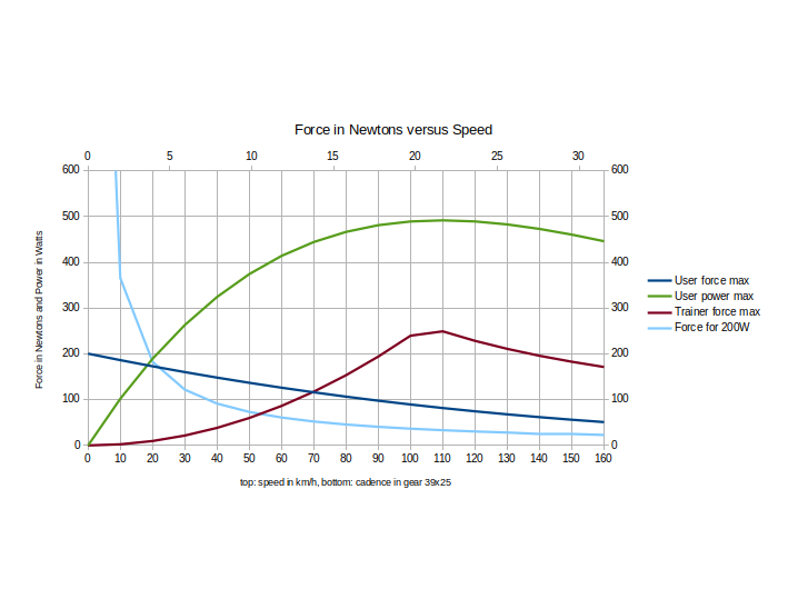
Figure 1: Trainer maximum resistance and rider maximum force
Virtual gears
When virtual gears are used, because the trainer cannot apply the desired resistance, or the rider wants a wider gear range than available on the bicycle, some adaptations are required. The power is not changed, but the force required from the rider, and the simulated speed, are changed in proportion to the virtual gear ratio vgr. For example, with vgr=2, for the same rider power, f_p would be doubled, the rider would spin half as fast, and the device speed would be half as much, but the simulated speed would remain the same, just like with a gear change.
We can define the device speed and acceleration, v_d and a_d (actual speed of the trainer), and the simulated speed and acceleration, v_s and a_s (speed that would be encountered if the virtual gears were real). To properly account for the virtual gearing, forces f_a, f_s and f_r, and the simulated inertia m_e * a, are all calculated with the simulated speed and acceleration, v_s and a_s. However, the inertia actually encountered in the drive train and roller, or flywheel, is related to the device acceleration a_d.
v_s = vgr * v_d
f_p_vgr = f_p * vgr
f_p * v_s = f_p_vgr * Vd = f_p * vgr * v_s / vgr

f_brake = vgr * Fp(m, m_e, a_s, v_s, sl, cd_a_rho, w, c_rr) - m_f * a_d
On a trainer that accepts a force as input, like the Fortius, this formula provides the brake resistance to apply. The speed reported by the trainer is then multiplied by vgr. On a trainer that accepts other input parameters such as the slope, the slope needs to be compensated (i.e. sl_c) in order to achieve the desired brake resistance.
Stalling or stuttering
There are two special cases to consider, because they can cause problems when riding on a trainer. Several curves are shown in Figure 1 to illustrate these two cases. The vertical axis is the force in Newtons, for most curves, and the power in Watts for the green curve. The horizontal axis is the speed in km/h, and the corresponding cadence in rpm, assuming a 39 teeth chainring, 25 teeth cog and 700x25 wheel and tire. The red curve represents the maximum resistance that the trainer can produce. The dark blue curve illustrates the maximum force that the rider can apply on 175mm cranks, for some typical rider [7]. The green curve is the corresponding maximum power that this typical rider can produce. Finally, the pale blue curve shows the force needed to produce a target power of 200W at different speeds.
The first case to consider is the force required, in target power mode, at slow speed. Indeed, the force tends to infinity as the speed approaches zero. In Figure 1, we can see that the force required to produce 200W (pale blue curve) is larger than the maximum force that the rider can produce for that gear ratio (dark blue curve) until the speed reaches a little less than 5km/h. For this reason, in target power mode, a maximum resistance is imposed, below a certain speed, to avoid stalling the rider. Note that in this case, the trainer is not capable of opposing a strong resistance at low speed anyway.
The second case may arise when the rider is starting, or riding at low speed, and encounters a very large slope. Below a certain speed, the maximum resistance opposed by the trainer is limited (red curve) and thus lower than the maximum force that the rider can push (dark blue curve). Assuming that the slope is very steep and that the trainer is at its limit resistance, the speed should stabilize at around 14 km/h in that example, where the two curves meet. At that point, the maximum user force is equal to the trainer resistance. However, such systems with a control loop may oscillate around the equilibrium value, causing stuttering.
In many cases, at these high resistance values, stuttering will be caused by tire slippage. The rider must ensure that the tire and roller are clean, free from oil, and that the pressure of the roller on the tire is sufficient. If stuttering is still present, this can be explained by the delay in the feedback loop, and the amplitude of the correction (correction gain). Below 14 km/h, the rider can still accelerate and may reach 16 or 17 km/h before the trainer force is corrected and increased. At that point, the force will be too high and the rider will slow down, possibly as low as 12 km/h before the trainer resistance is lowered, and this can continue in a painful oscillation. Of course, when riding in real life, this does not happen, because there is no feedback loop delay, and because the rider inertia prevents quick changes in speed. One solution to prevent this is to limit the rate at which the brake resistance is increased. This is the equivalent of a low gain value in a PID control loop [8]. In that case, it takes more time to reach the correct value but oscillations, associated with a high gain, are avoided.
[1] https://betterbicycles.org/bicycle-power-calculations/
[2] David Gordon Wilson, Bicycling Science, third edition, The MIT Press, March 19 2004, ISBN-13 : 978-0262731546.
[3] https://en.wikipedia.org/wiki/Density_of_air
[4] https://github.com/totalreverse/ttyT1941/wiki
[5] https://en.wikipedia.org/wiki/Moment_of_inertia
[6] http://www.uucmotorwerks.com/flywheel/flywheel_mass_calcs.pdf