PSU Setup - Geowissenschaften/EXCISS GitHub Wiki
The following step by step instruction must be executed, to change some of the factory default values, to match the exciss requirements.
Required hardware
Software preparation
Install bqStudio:
BatteryManagementStudio-1.3.54.1_Build1 (sluc525u)
Update bqStudio Chemistry Database:
- download: bqStudio Chemistry Updater (Rev. EE) - ChemUpdate632 (sluc564dw)
- copy files in
Chemitryfoler to:..\TI\BatteryManagementStudio\chemistry
Update Charger definiton:
- download: Charger_1_00-bq25700A.bqz
- copy to:
..\TI\BatteryManagementStudio\config\
Update Gauge definition:
- download: bq40z50-R2 Gauging Embedded Firmware v2.11 (sluc649)
- copy:
4500_2_11-bq40z50R2.bqzto..\TI\BatteryManagementStudio\config\ - use:
bq40z50R2_v2_11_build_52.srecfor fimware update (description below)
Change bqStudio View Type
- In the
Windowmenu selectPreferences - click on
All Global Settings - under
Battery Management Studio (bqStudio) View Typechoose:Show Advanced Views
Charger
The charger IC doesn't require to be prepared. All the pre define parameters are define as hardware based values. Some parameters must be defined during runtime by the MCU.
Gauge Preparation
The gauge IC requires some preparation before first usage. Follow the step by step instruction to prepare the gauge before productive usage.
-
Connect PSU's SMBus TI EV2400 USB Adapter.
-
Power up PSU
Gauge firmware update
- Start bqStudio
- select
gaugeand click next - select
4500_2_11-bq40z50R2.bqzand clickFinish - click
OK - click
Firmware - select
bq40z50R2_v2_11_build_52.srec(mentioned above in Software preparation: Update Gauge definition) - click
Program - restart bqStudio
Gauge battery parameters
Update cell chemistry
A chemistry database update might be required to add the required chem-id(2152) (mentioned above in Software preparation: Update bqStudio Chemistry Database:)
- select chemid: 2152
- click on
Update Chemistry from Database
Update Gas Gauging parameters
-
click
Data Memory -
click
Gas Gauging -
set
Design Capacity mAh(underDesign) to:3500mAh -
set
Design Capacity cWh(underDesign) to:5089cWh(Nominal Voltage (V) * cell count * capacity(Ah) * 100 =
3,635V * 4 * 3,5Ah * 100 = 5089cWh)
-
set
Design Voltage(underDesign) to:14540mV(Nominal voltage (mV) * cell count)
-
set
Chg Current Threshold(underCurrent Thresholds) to:30mA -
set
Term Voltage(underIT Cfg) to:12000mV(3000mV * cell count)
-
set
Load Mode(underIT Cfg) to:1(constant power)
Advanced Charge Alorithm parameters
- click
Data Memory - click
Advanced Charge Alorithm - set
Charge Term Taper Current(underTermination Config) to:50mA
Considerations
We need to ensure:
- Taper Current > Chg Current Threshold > Quit Current
- Dsg Current Threshold > Quit Current
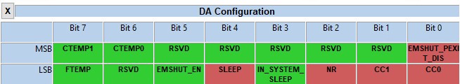
Gauge change DA Configuration (0x0012 -> 0x0117)
SLUUBK0A page 150
-
click
Data Memory -
click on
Settings -
click on
DA Configuration(underConfiguration) -
toggle
NR(red)NR (Bit 2) = 1 (Use PRES in system detection: NON-REMOVABLE mode)
-
toggle
CC0(red)CC1, CC0 (Bit 1,0): Cell Count set to CC1 = 1, CC0 = 1 (Cell Count: 4 cell)
-
toggle
EMSHUT_PEXIT_DIS(red)EMSHUT_PEXIT_DIS (BIT 8) = 1 (Prevents usage of SHUTDN pin as exit option)
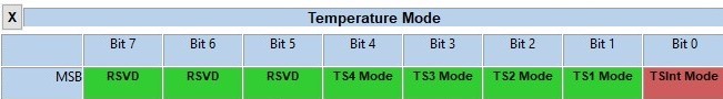
Gauge change Temperature Mode (0x0004 -> 0x001)
SLUUBK0A page 149
-
click
Data Memory -
click on
Settings -
click on
Temperature Mode(underConfiguration) -
toggle
TS2 Mode(green)TS2 Mode (Bit 2) = 1 (Cell temperature)
-
toggle
TSInt Mode(red)TSInt Mode (Bit 0) = 1 (FET temperature)
Gauge change Temperature Enable (0x0006 -> 0x01f) 1e
SLUUBK0A page 148
-
click
Data Memory -
click on
Settings -
click on
Temperature Enable(underConfiguration) -
toggle
TSint(red)TSint (Bit 0) = 1 (Enable internal TS)
-
toggle
TS3(red)TS3 (Bit 3) = 1 (Enable TS4)
-
toggle
TS4(red)TS3 (Bit 4) = 1 (Enable TS4)
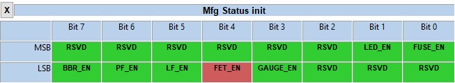
Gauge Mfg Status init (0x0000 -> 0x0010)
SLUUBK0A page 161
-
toggle
FET_EN(red)FET_EN (Bit 4) = 1 (All FET Action: Enabled)
-
Power cycle PSU
Gauge change FET Options (0x0020 -> 0x0024)
SLUUBK0A page 138
- click
Data Memory - click on
Settings - click on
FET Options(underConfiguration) - toggle
OTFET(red)
OTFET (Bit 2) = 1 (CHG and DSG FETs will be turned off for overtemperature conditions)
Gauge Calibration
Explained at the end of this page
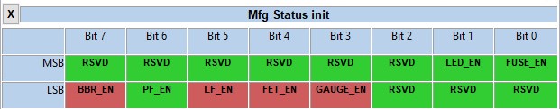
Gauge Mfg Status init (0x0010 -> 0x00b8)
SLUUBK0A page 161
This step proberbly should be done AFTER learning cycle, but we did perform the lerning cycle later. Refer to: TI Support Forum: BQ34Z100-G1: Learned Status
-
click
Data Memory -
click on
Settings -
click on
Mfg Status init(underManufacturing) -
toggle
BBR_EN(red) BBR_EN (Bit 7) =1 (Black Box Recorder: Enabled) -
toggle
LF_EN(red) LF_EN (Bit 5)= 1(Lifetime Data Collection: Enabled) -
toggle
GAUGE_EN(red) GAUGE_EN (Bit 3) =1 (Gauging: Enabled) -
Power cycle PSU
Gauge Perform Learning Cycle
This is described in: 4024.LearningCycleOverview.pdf
Please note: “The learning cycle guide doesn't 100% apply to bq40z50-R1 in terms of some of the flag names. It's more a procedure guide. RDIS is RUP_DIS flag.”
Source: TI Support Forum: BQ40Z50-R1: Problems performing a Learning Cycle
Gauge Calibration (needs to be performed earlier, see above)
Voltage Calibration:
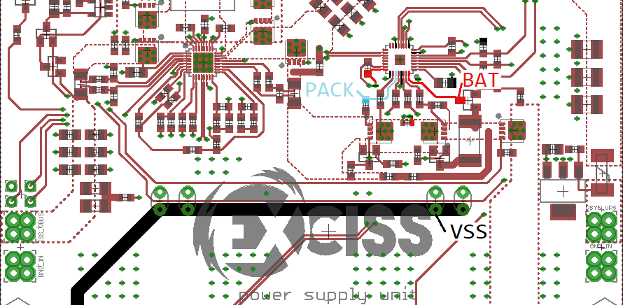
- connect 4 100 Ohm resitors as battery dummys
- apply 16V between VSS and 4P
- Measure Cell 1 Voltage and enter value in calibration field
- tick
Calibrate VoltageCheckbox - Measure BAT pin voltage and enter value in calibration field
- tick
Calibrate VoltageCheckbox - measure PACK pin voltage and enter value in calibration field
- tick
Calibrate VoltageCheckbox - Click
Calibrate Gas Gauge
Current Calibration
- set DC load to 900mA and connect to PSU output
- connect 5V to PSU input
- disconnect EV2400
- start bqStudio
- click on
Charger - click on
Next - click on
Charger_1_00-bp2700A.bqz - click on
Finish - reconnect EV2400
- click on
Read Register - set Input Current Register to 0mA
- restart bqStudio
- Click on
Calibration - Enable DC load
- Disconnect 5V at PSU input
- enter measured current (should be 900mA) into
Applied Curennt(example: -900) - tick
Calibrate CurrentCheckbox - Click
Calibrate Gas Gauge
Temperature Calibration
- apply know temperature to all sensor
- enter temperature in
Tempearturefield - Hit
CalibrateCheckbox - Click
Calibrate Gas Gauge