Component risk evaluations - Geowissenschaften/EXCISS GitHub Wiki
Following chart gives a overview of the electrical components. Each components, and the associated data or power path, are evaluated regarding mission criticality. Each of this nodes are indexed, and should be evaluated regarding criticality, side effects in a event of failing, possible counter measures etc.
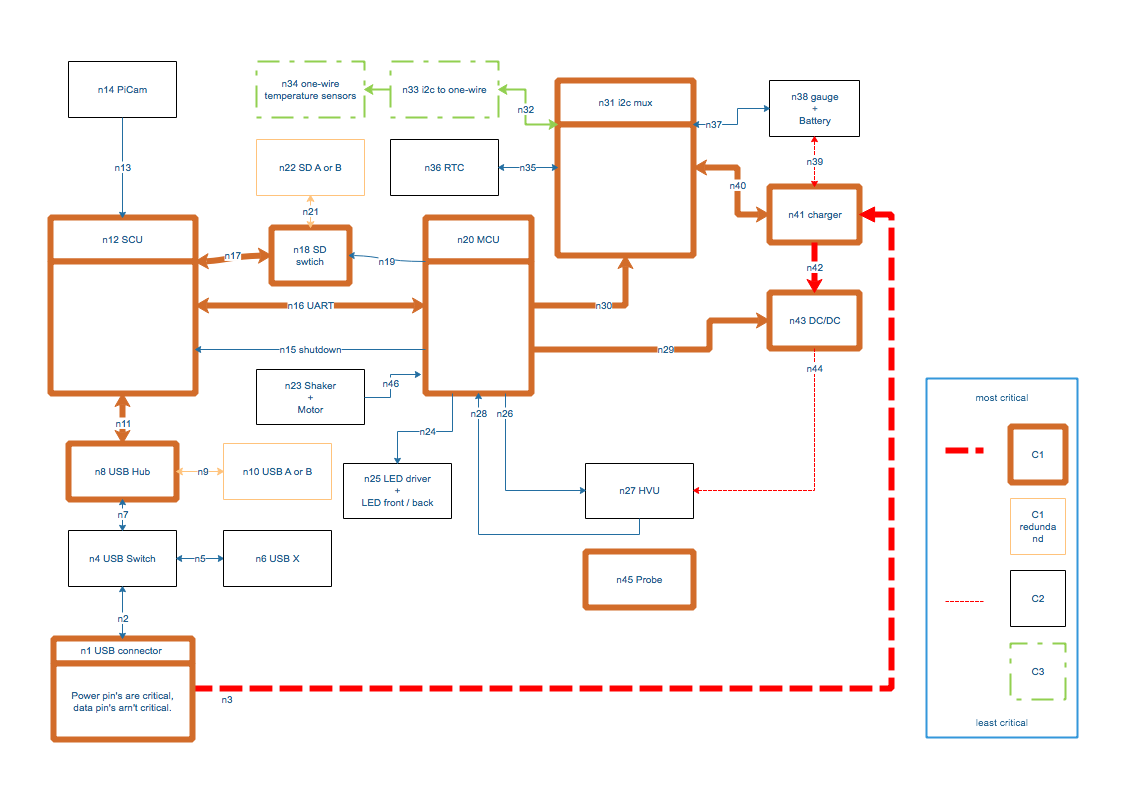 (image a.1 - component risk evaluation)
The most critical components, or lines, are marked with thickest lines, and marked as C1 nodes. If one of the C1 category nodes fails, the whole system is expected to fail. If a temporary glich in some of the component is the root cause, a usb power cycle might help to recover the system.
C2 nodes failures are critical failures, but doesn't cause a complete failure of the whole system. For example, if one, or both, LED light sources fails and doesn't illuminates the chamber, the image recording are heavily limited, but the experiment can be still continued.
Some C1 nodes, SD and USB storage A/B, are redundant, and do automatically fail over to the spare component.
Each C1 and C2 nodes should be analysed and reviewed against:
- Is it possible to harden against failures?
- How can be determined the health status of the component?
- In a event of a failure detection, what can be done to regain normal operating state. (Subsystem power cycle for example)
- Any development of counter measure must be checked whether is worth it. For example, if the failed component can be recovered by simple power cycle, no extra developing effort is required.
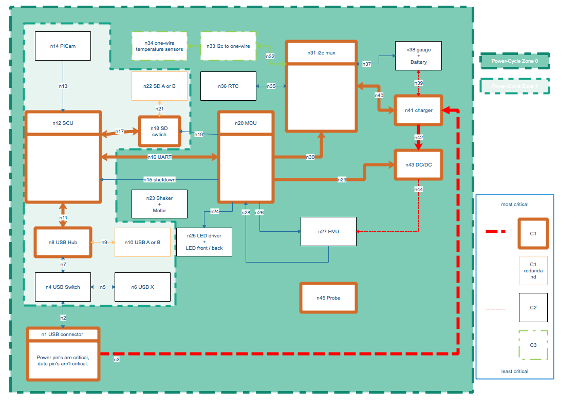 (image a.2 - component power-cycle zones)