2. Hardware - Geowissenschaften/EXCISS GitHub Wiki
In the experiment, forsterite dust particles will be levitating between two electrodes in micro gravity and be exposed to ~100 electrical discharges over 30. The particles in the ionized channel will melt partly or completely, collide and form aggregates. The experiment will be performed on board of the ISS in a NanoRacks NanoLab shown in the Figure.
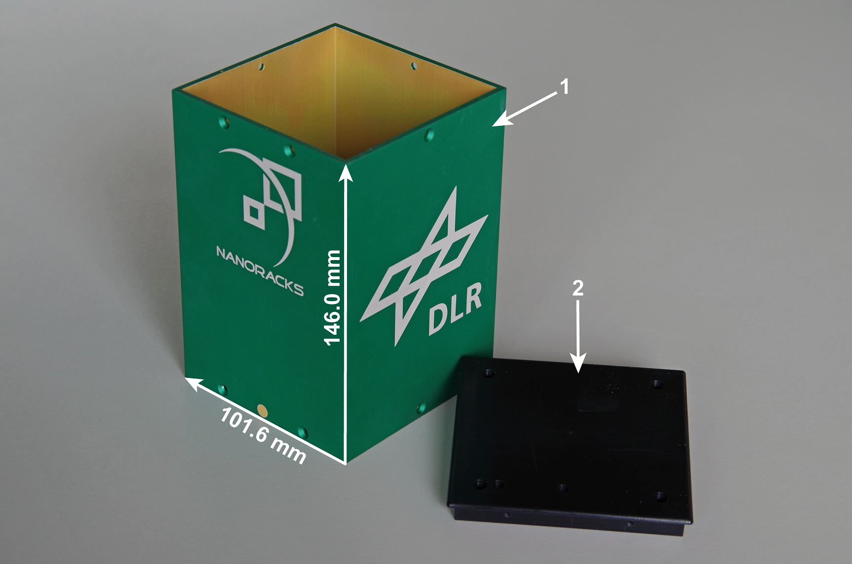
- NanoRacks NanoLab
- end cap
The NanoLab is provided by the Deutsches Zentrum für Luft und Raumfahrt (DLR) and its dimensions are 146 mm x 101.6 mm x 101.6 mm. On board of the ISS, the NanoRacks NanoLab will be connected to FRAME (NanoRacks computer aboard ISS). It is connected via an USB 3.0 port with a maximum current of 900 mA at 5 V.
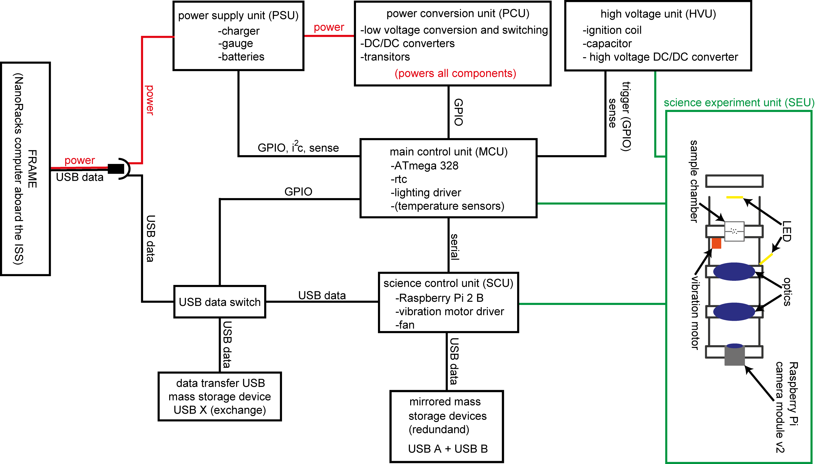
To create an overview of the experimental setup a block diagram of the components is shown in the Figure. The experimental setup can be divided in six units by function: the power supply unit (PSU), the power conversion unit (PCU), the main control unit (MCU), the science control unit (SCU), the science experimental unit (SEU) and the high voltage unit (HVU).
The Bill of Materials (BOM) lists all used materials with a short description and the technical data sheet and can be downloaded: BOM
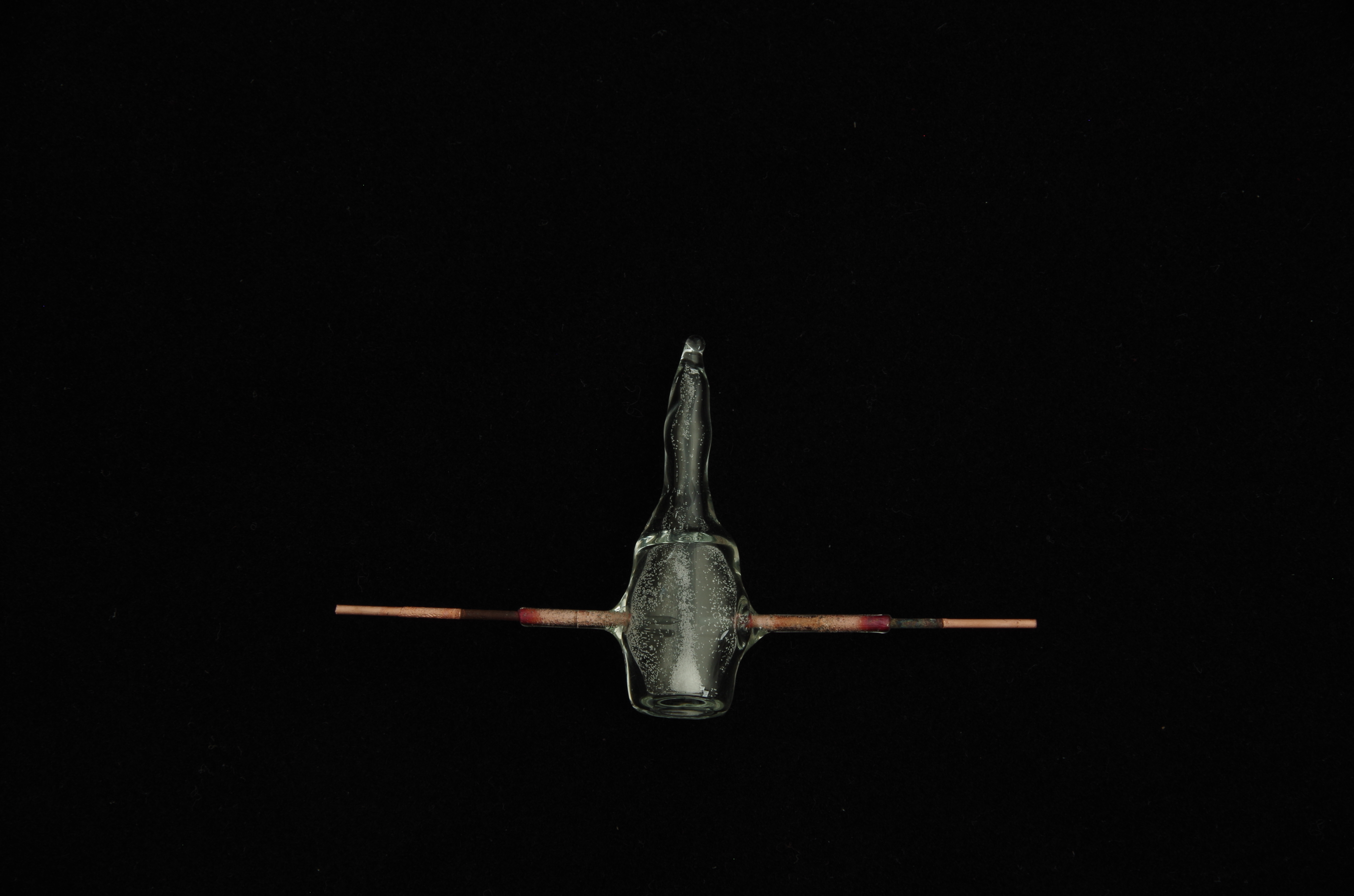
The sample chamber consists of glass. Two electrodes are embedded on opposite sides. For the final setup the metal of the electrodes is still being determined. It will probably consist of tungsten. The Figure shows a sample chamber with iron electrodes. In the contact region to the glass they are alloyed with copper. The present two electrodes have a diameter of 0.5 mm and a distance of 3 mm.
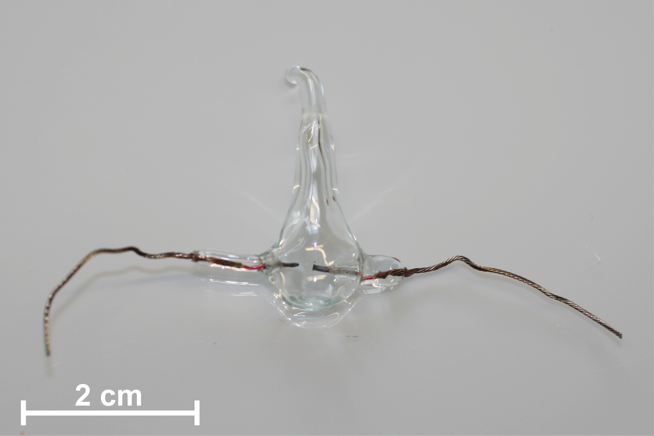
The sample chamber was manufactured by the company NORDLICHT, located in Friedrichsdorf (Germany). It is filled with the gas argon with a pressure of ~100 mbar. The sample chamber will also include Mg2SiO4 particles.
Below, a picture of the sample chamber as in state of july/2018
The main parts of the optical setup are a tube lens and an EC Epiplan Neofluar 2.5x/0.06 objective manufactured by ZEISS. Furthermore, the Science Experimental Unit (SEU) includes a camera, a sample chamber, two LED holders and a vibration motor. A photograph of the components of the SEU is shown in the Figure. It shows the SEU as an exploded view.
For video recording a Raspberry PI camera v2 is used. The sample chamber is illuminated by two LEDs, one from the front and one from the back. The vibration motor is mounted on the holder of the sample chamber. All optic components were mounted in the LINOS Microbench system from QIOPTIQ. They were fixed with screws and epoxy glue. The sample chamber is fixed in its holder with epoxy glue. The LEDs were glued with thermoconductive epoxy glue in their holders. The backlight LED has a diffuser made of acrylic glass. The size ot the SEU without the front LED holder is roughly 14.2 cm x 4 cm x 4 cm. A schematic drawing of the assembled SEU components is shown in the Figure. The SEU is fixed with screws in a 3D-printed holder. Together with the HVU it is mounted on a wall of the NanoRacks NanoLab.
- Raspberry Pi camera
- optics (lens)
- optics (tubus lens)
- sample chamber
- electrodes
- back light LED with diffuser
- front light LED
- vibrating motor
For the final optics setup the components were glued for stability. The figure below shows the latest state of the optics from july/2018
The HVU can be divided by function into six parts:
- Core circuits
- ignition spark generation
- arc burning time extension
- Auxiliary circuits
- ignition capacitor charging
- ignition trigger
- arc capacitor charging
- arc capacitor voltage measurement
- supply voltage generation
The core circuits of the HVU (1a) and (1b) are generating the arc discharge in the sample chamber. The auxiliary circuits part (3) and (5) are connected to the main control unit. Parts (2), (4) and (6) serve as power supply. A simplified circuit diagram of the core circuits of the HVU is shown in Figure 3.7. The complete HVU including auxiliary circuits (2) to (6) is shown in the previous Figure at the end of this section. The left hand side of the following Figure shows the ignition spark circuit (1a), the right hand side the arc circuit (1b). During an experiment the HVU runs through the following duty cycle:
-
the DC/DC converter with 600V output is enabled to generate the charging voltage
-
charging of the ignition spark capacitor (Cigns) and the arc capacitor (Carc) arc igns begins
-
after 500ms Cigns reaches ~350V and is fully charged
-
Carc is still being charged and its voltage is measured continuously
-
Diode 2 (Darc) is conductive and Diode 1 (Digns) blocks. This protects the ignition coil (Tigns) from the Carc voltage
-
when Carc reaches its target voltage (adjustable upto 600V) arc the main control unit triggers the ignition spark the thyristor Thigns becomes conductive
-
Tigns generates a high voltage peak on its secondary side (up to 14 kV igns without the sample chamber being connected)
-
Digns becomes conductive while Darc blocks. This protects Carc from the Tigns voltage
-
when the voltage across the sample chamber reaches ~8 kV electrical breakdown occurs and the voltage decreases
-
immediately after the voltage has dropped below the Carc voltage Darc becomes conductive while Digns blocks
-
Carc is discharged through the ionized channel, created by the ignition arc spark in the sample chamber
The ignition spark has a duration of ~2µs. The duration of the arc depends on the charging voltage of the Carc and has a magnitude of ~500 µs. In conclusion Carc provides almost all of the arc energy. Other contributors can be neglected.

 Capacitors for the HVU, showing several states of ESD-save-packaging, from unpacked (left), to fully packed (right)
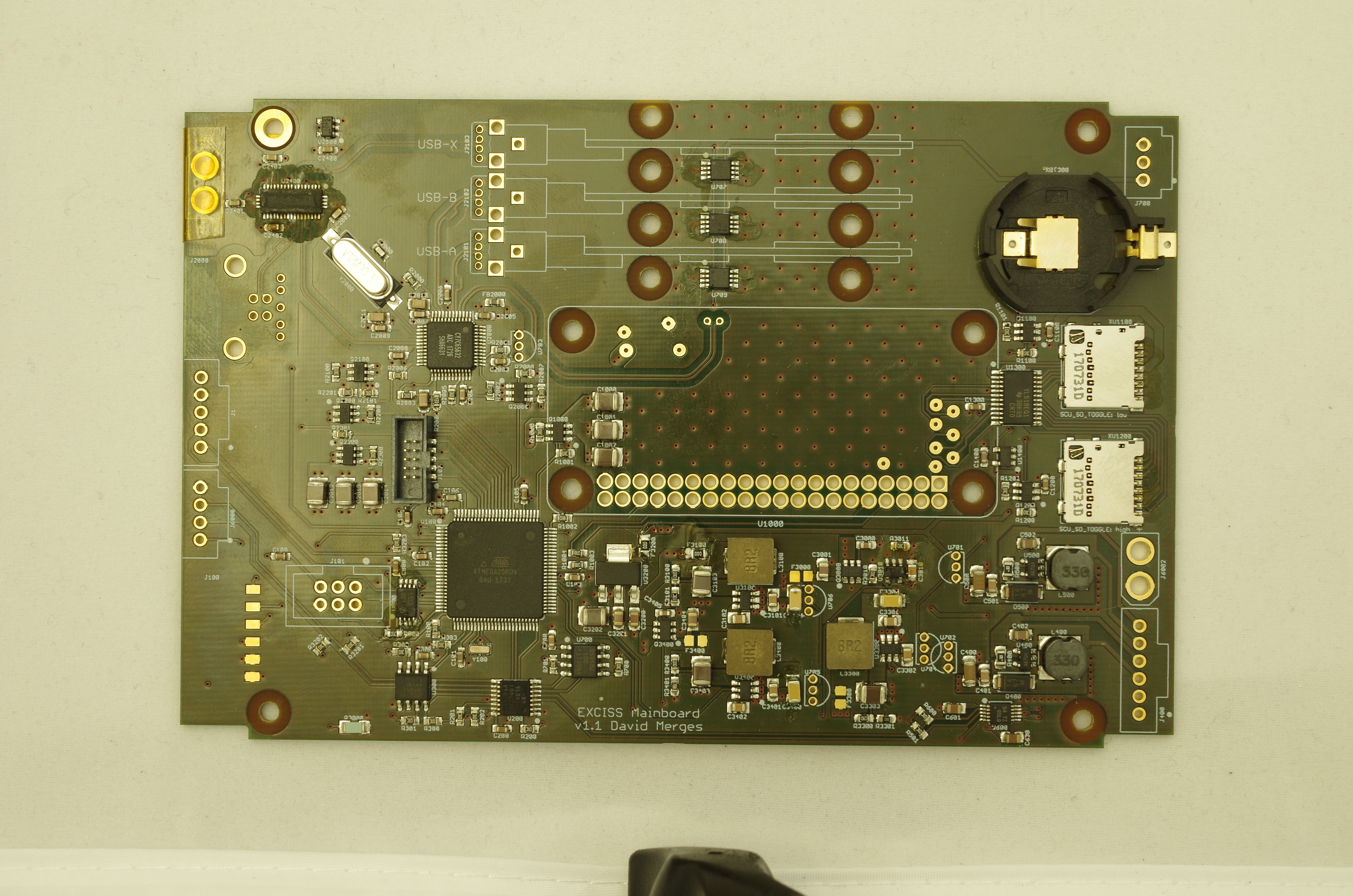
The following picture shows the MCU in its latest state from july/2018
 MCU, cleaned and assembled with plug connectors
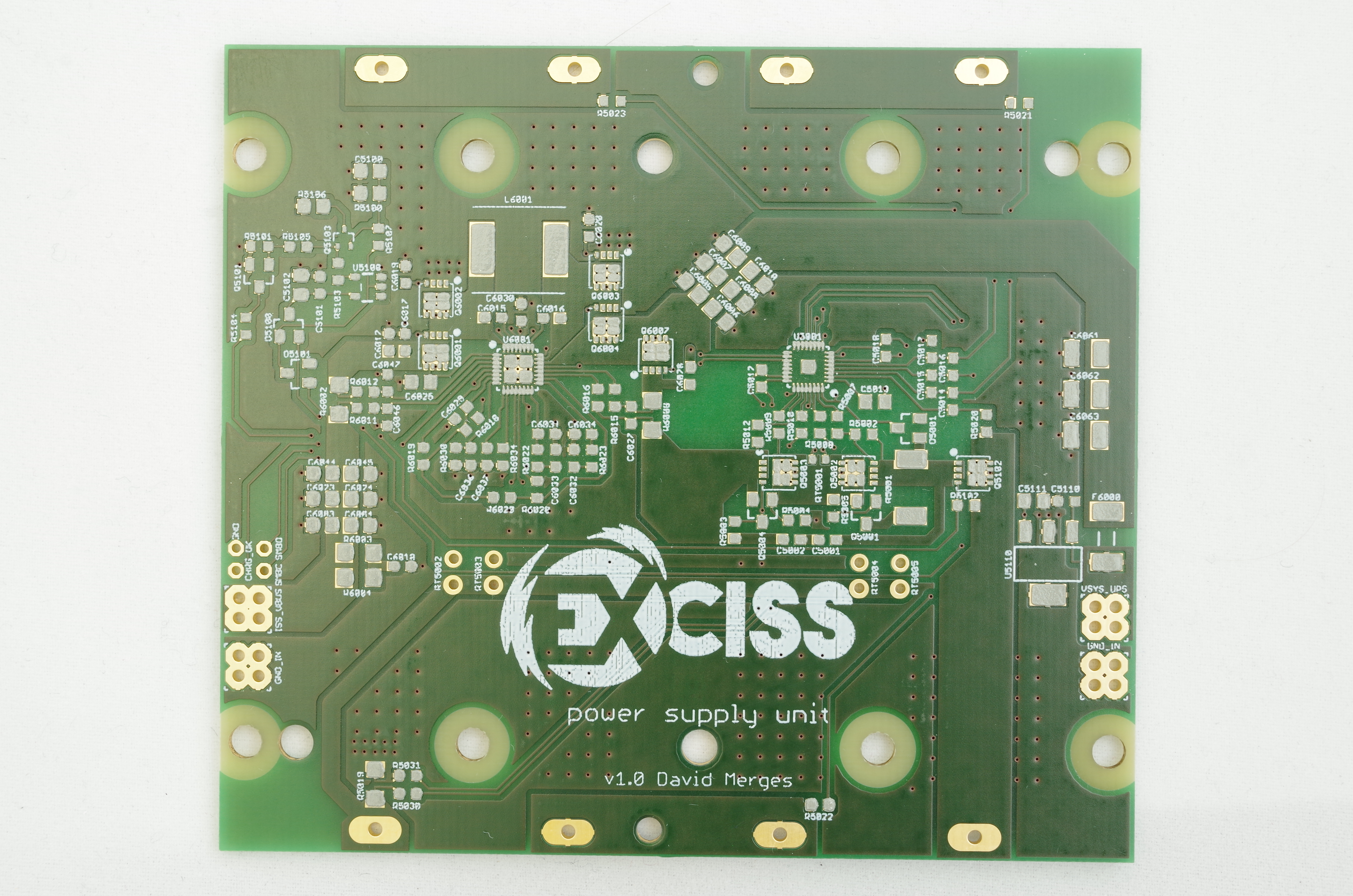
The following picture shows the PSU in its latest state from july/2018
 PSU, with reflow oven soldered parts and cleaned
The following pictures document the evolution of different parts of the EXCISS setup.
front view of the sample chamber
 back view of the sample chamber
 sample chamber with good view at the electrodes
 objective: Zeiss Epiplan Neofluar 2.5x/0.06 glued to holder
 tube lense, glued to holder
 optics and tube lense, glued to holder
 optics, objective, tube lense and camera sensor, objective and tube lense are glued, camera sensor can still be aligned
optics, fully assembled without sample chamber. Objective, tube lense and camera sensor are covered with an aluminum sheet.
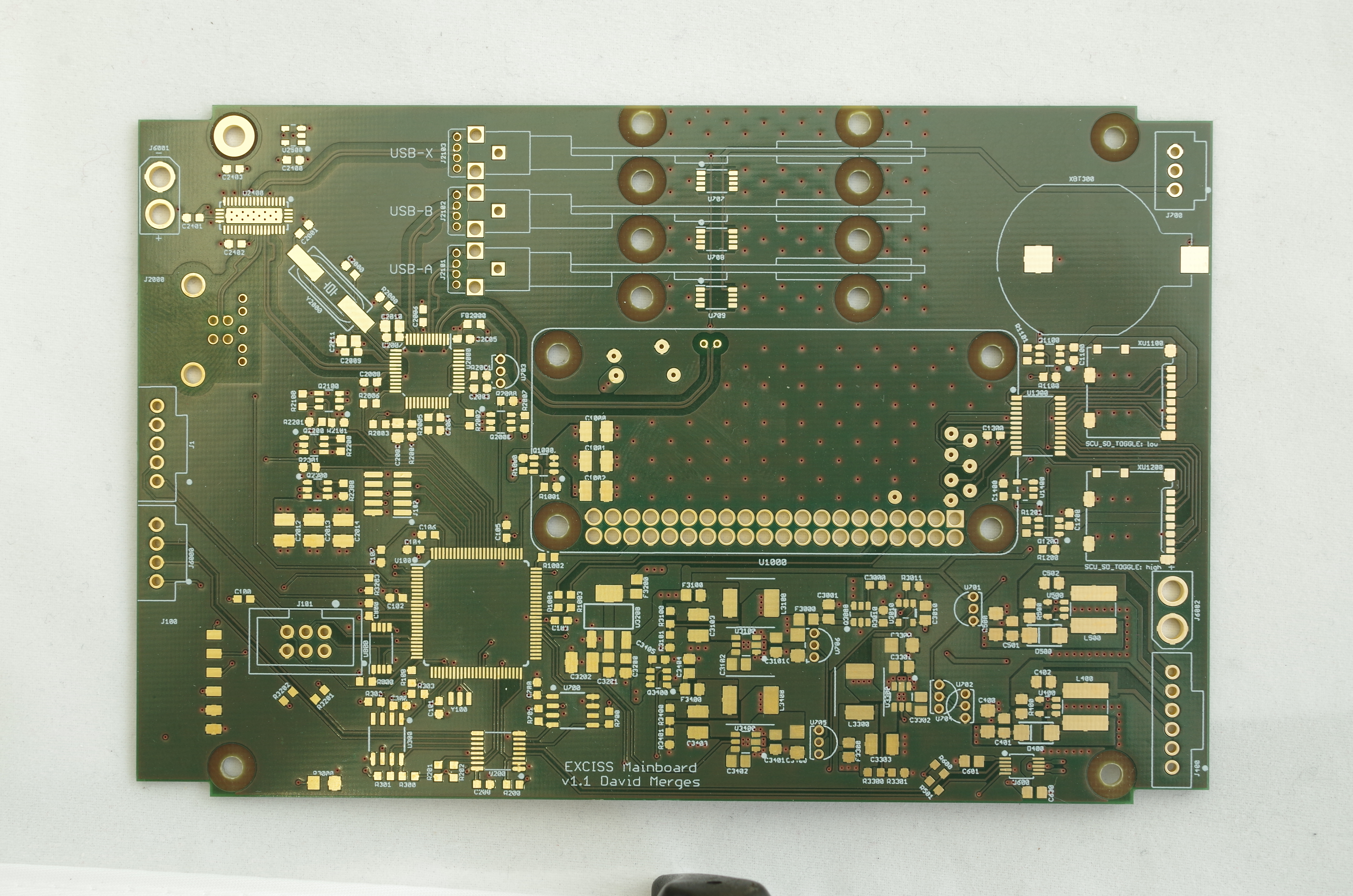 MCU pcb, clean and prior to assembly
 MCU, with reflow oven soldered parts, not cleaned
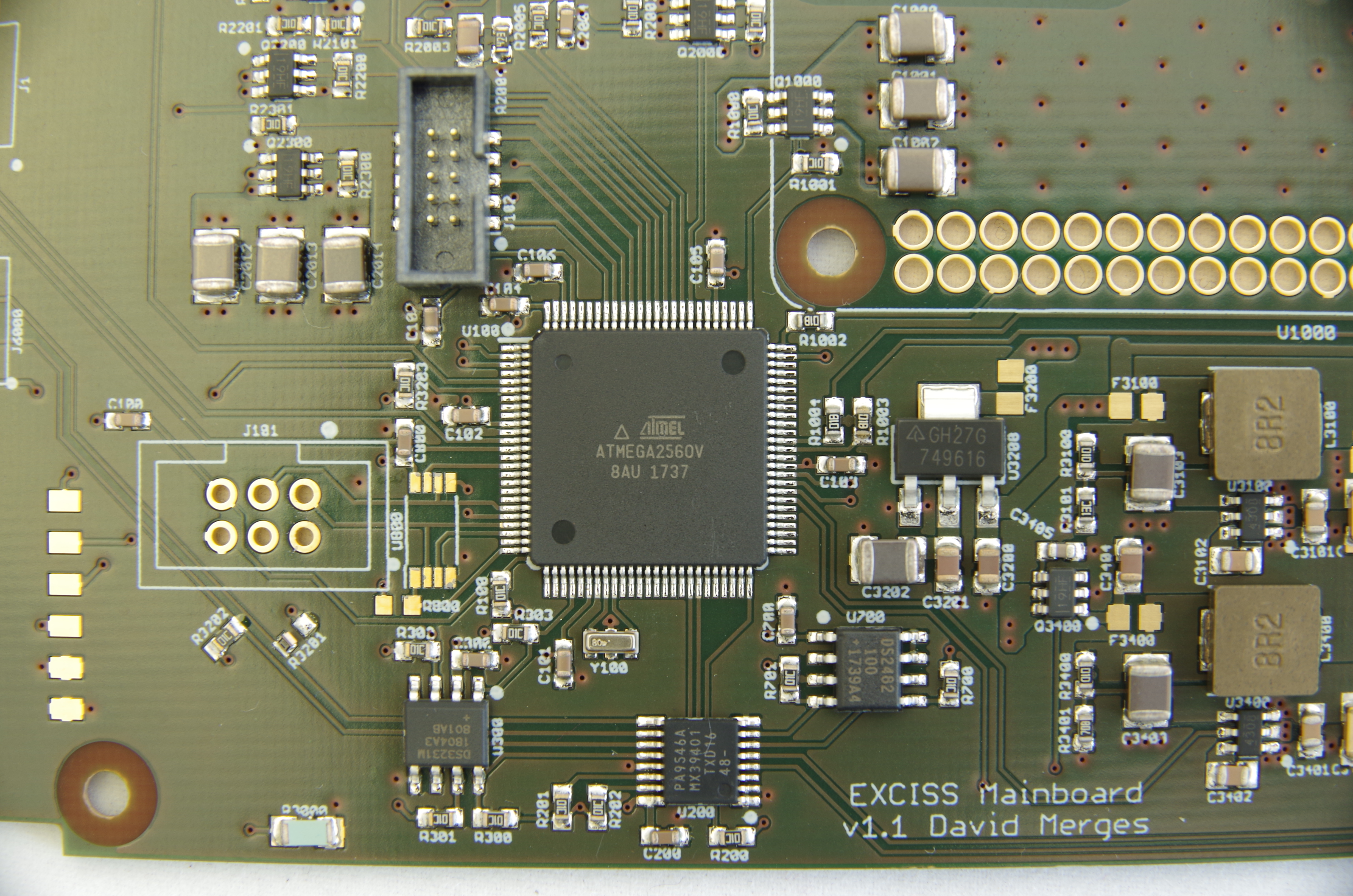 MCU, close up view on atmega
MCU, cleaned and assembled with plug connectors
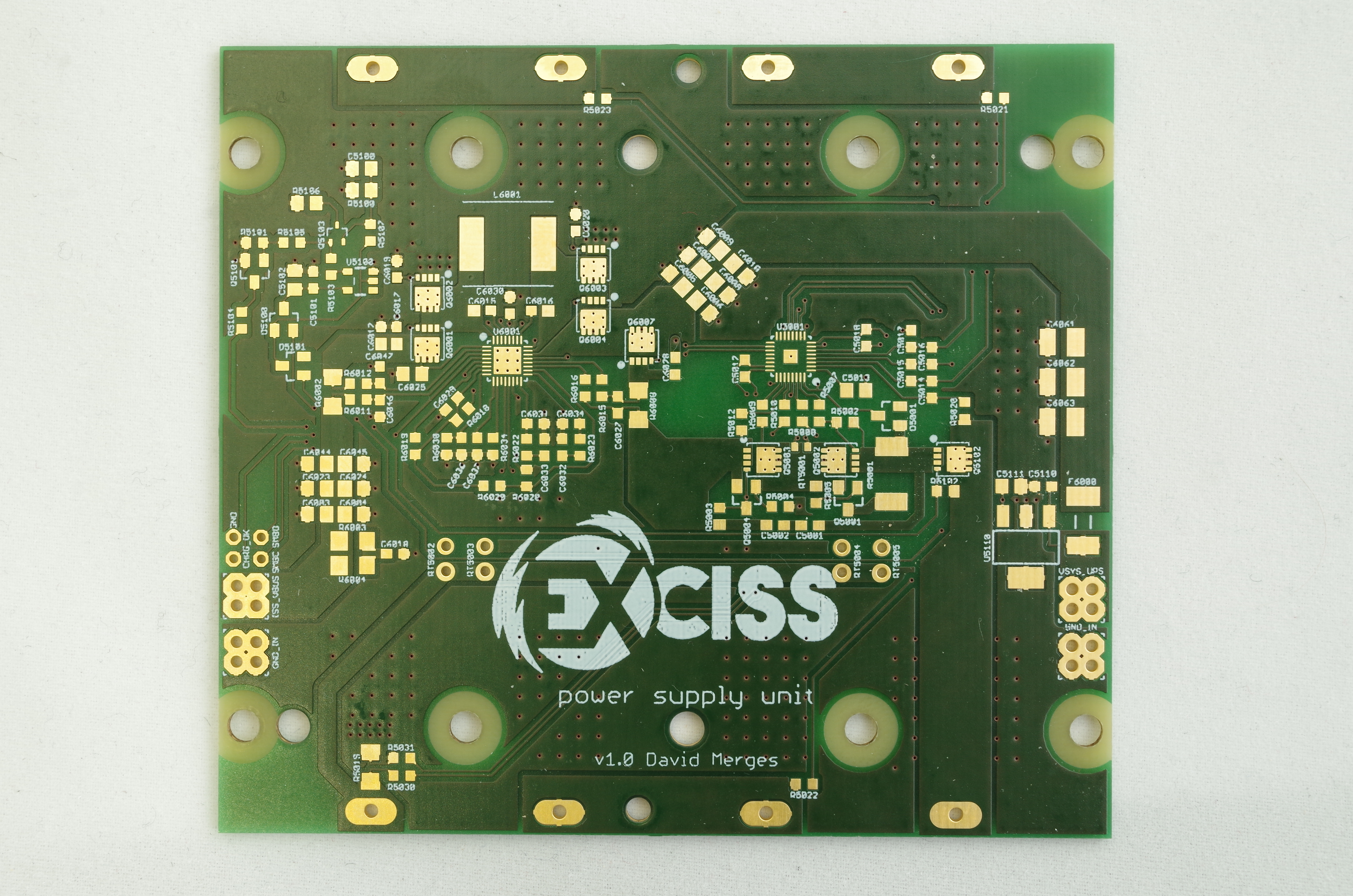 PSU, cleaned and prior to assembly
 PSU, with soldering paste
PSU, with reflow oven soldered parts and cleaned