Assembling Manufacturing - FreeYourStream/freedeck-wiki GitHub Wiki
After everything arrived the most fun part of the project can begin. This will explain the Through Hole Design, for all of you doing SMD, we don't think you need a guide on how to assemble your Freedeck
Picture with details on how to do everything will follow later.
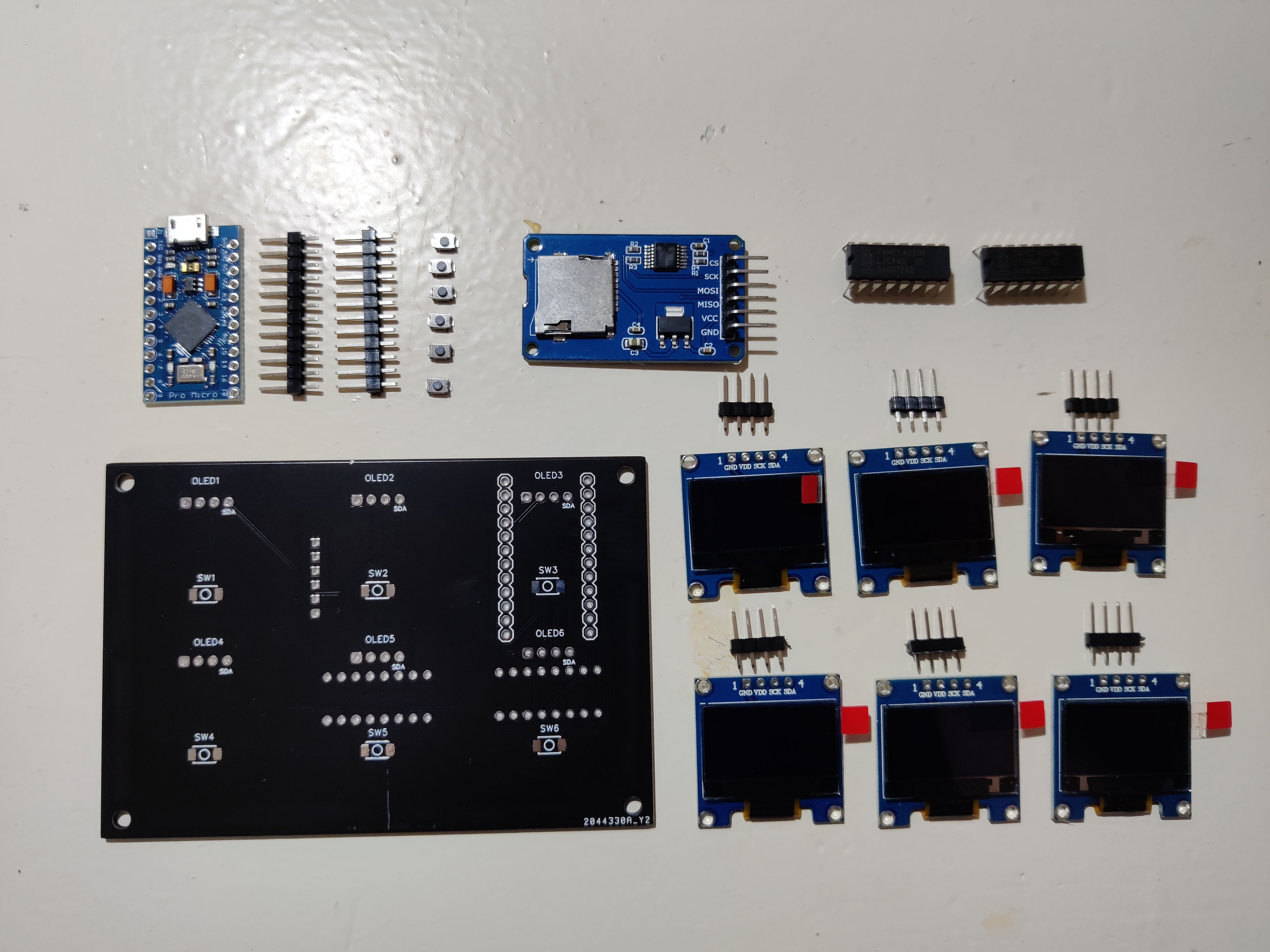
Step 1: Gathering components
Onces everything has arrived it's handy to gather everything so you don't have to search for it later. Needed tools:
- Soldering iron
- Tin
- Cutting tool
Tools that mighty be useful during assambling
- Soldering wick or Desoldering pump
- Helping hands (PCB holder)
- Tape
- A screen with this wiki
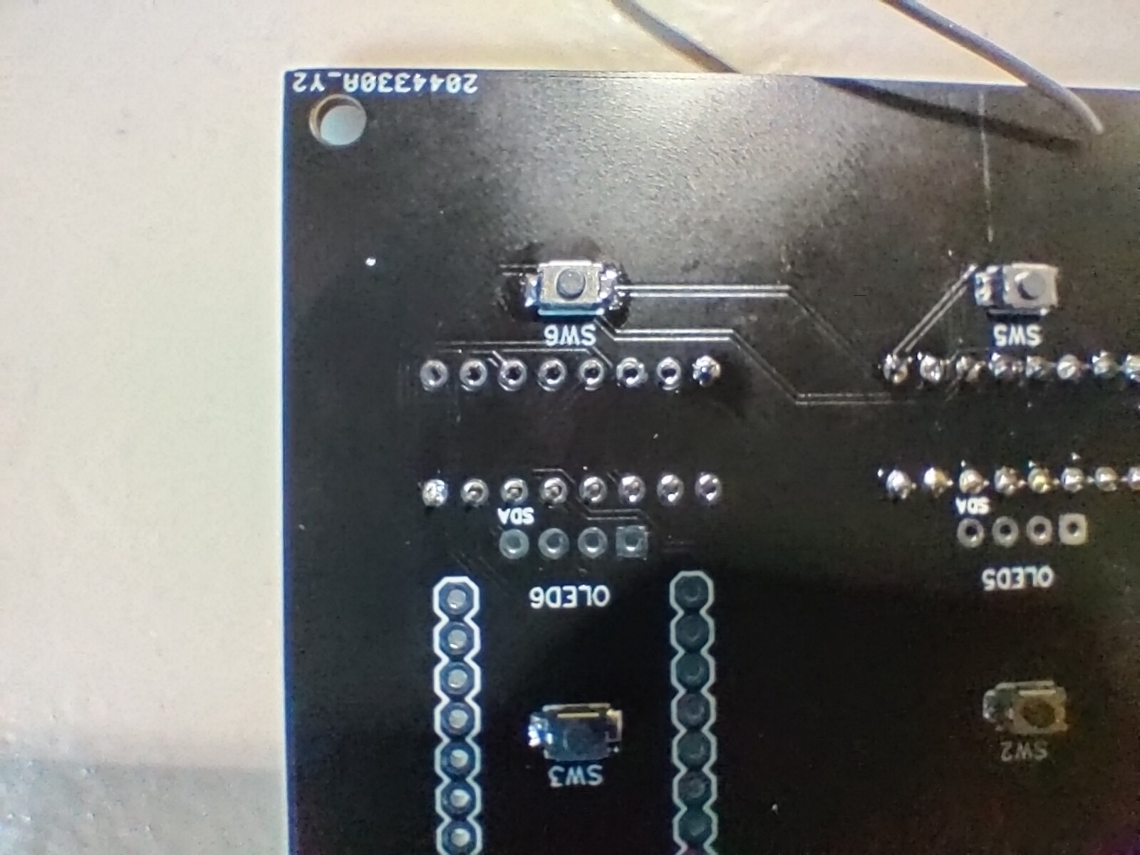
Step 2: Soldering the SMD buttons
We start with the hardest part of this build. Soldering the SMD buttons on to the PCB.
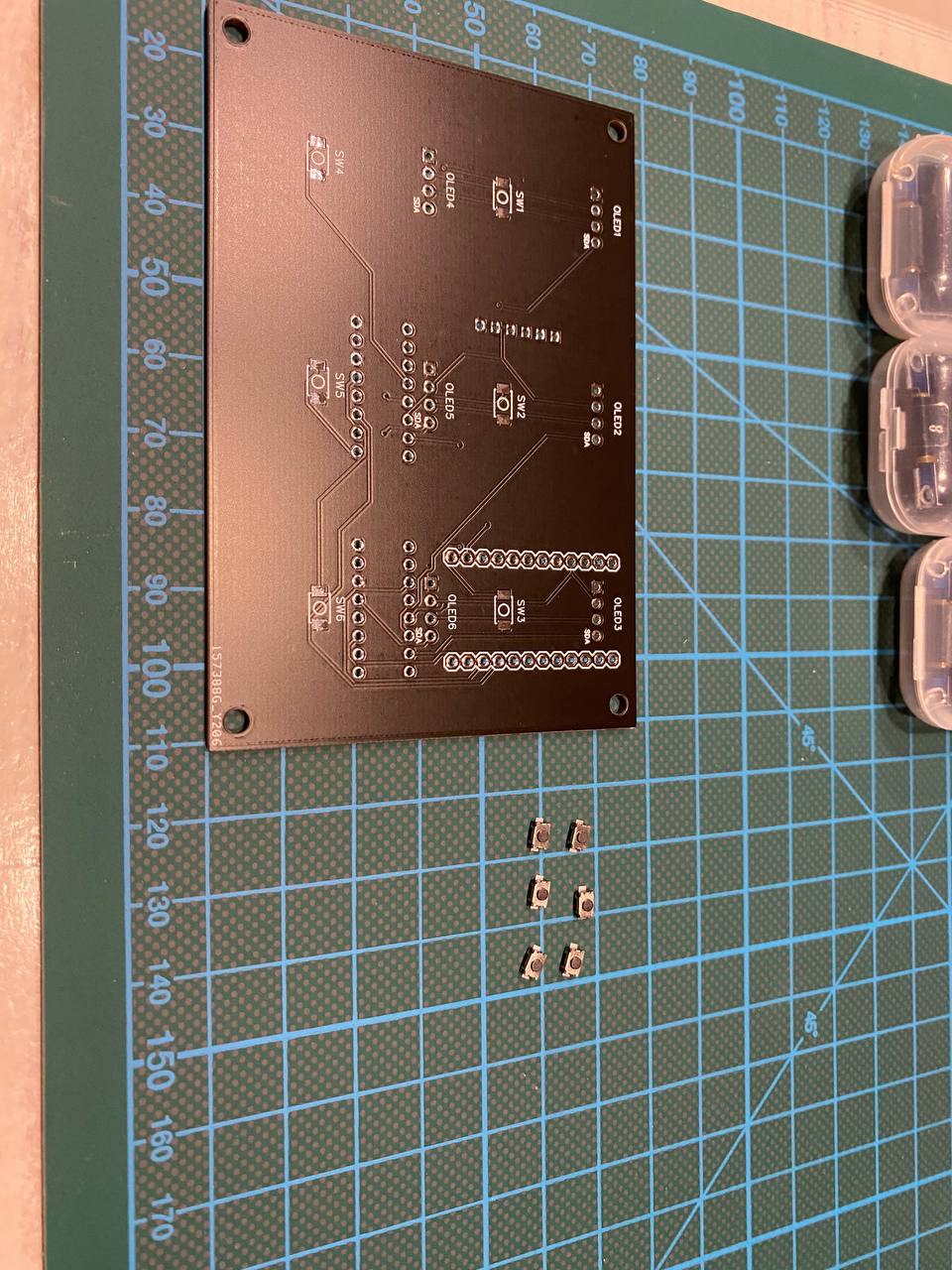
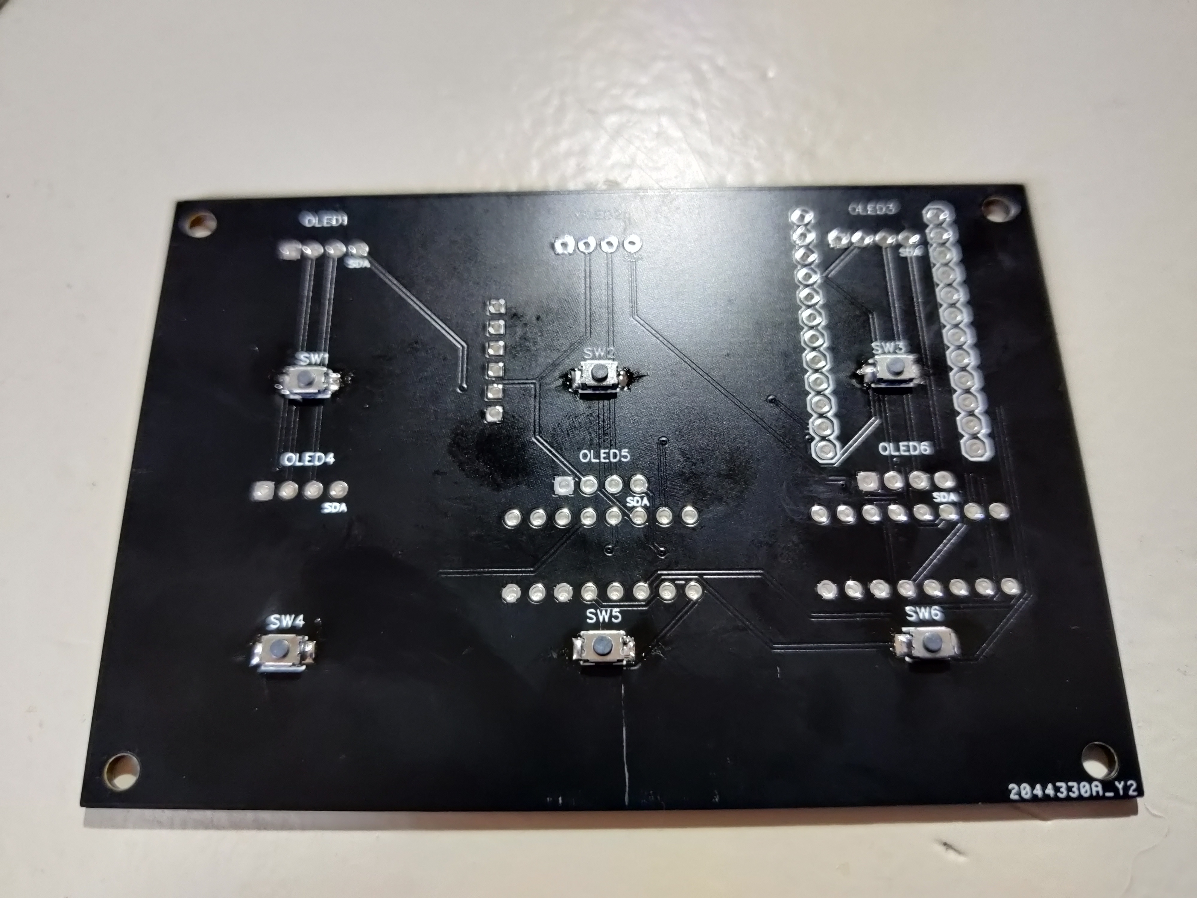
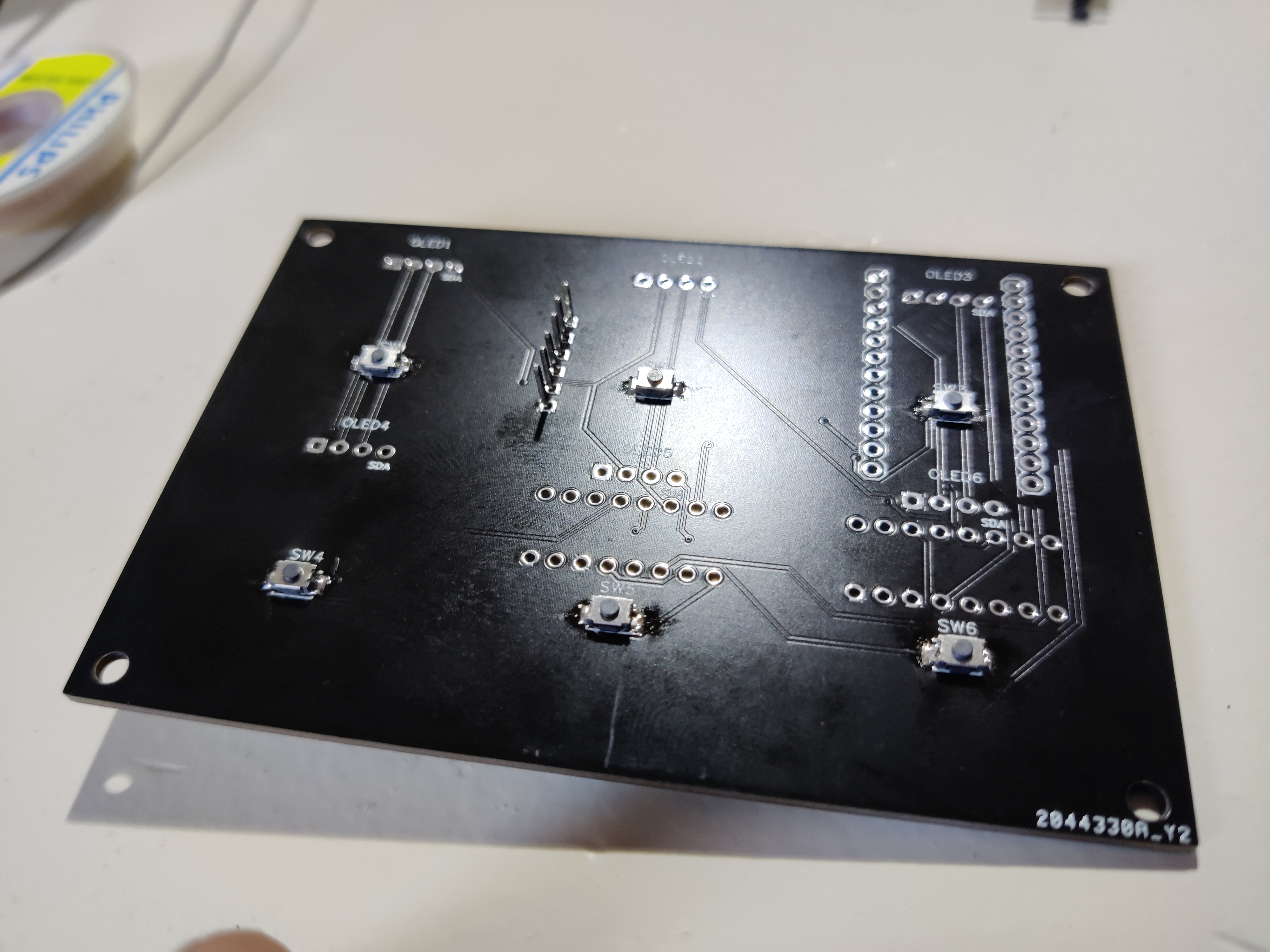
Start with your blank PCB
Pre-tin one pad (those silver shiny parts) per switch (as indicated by the SW label)
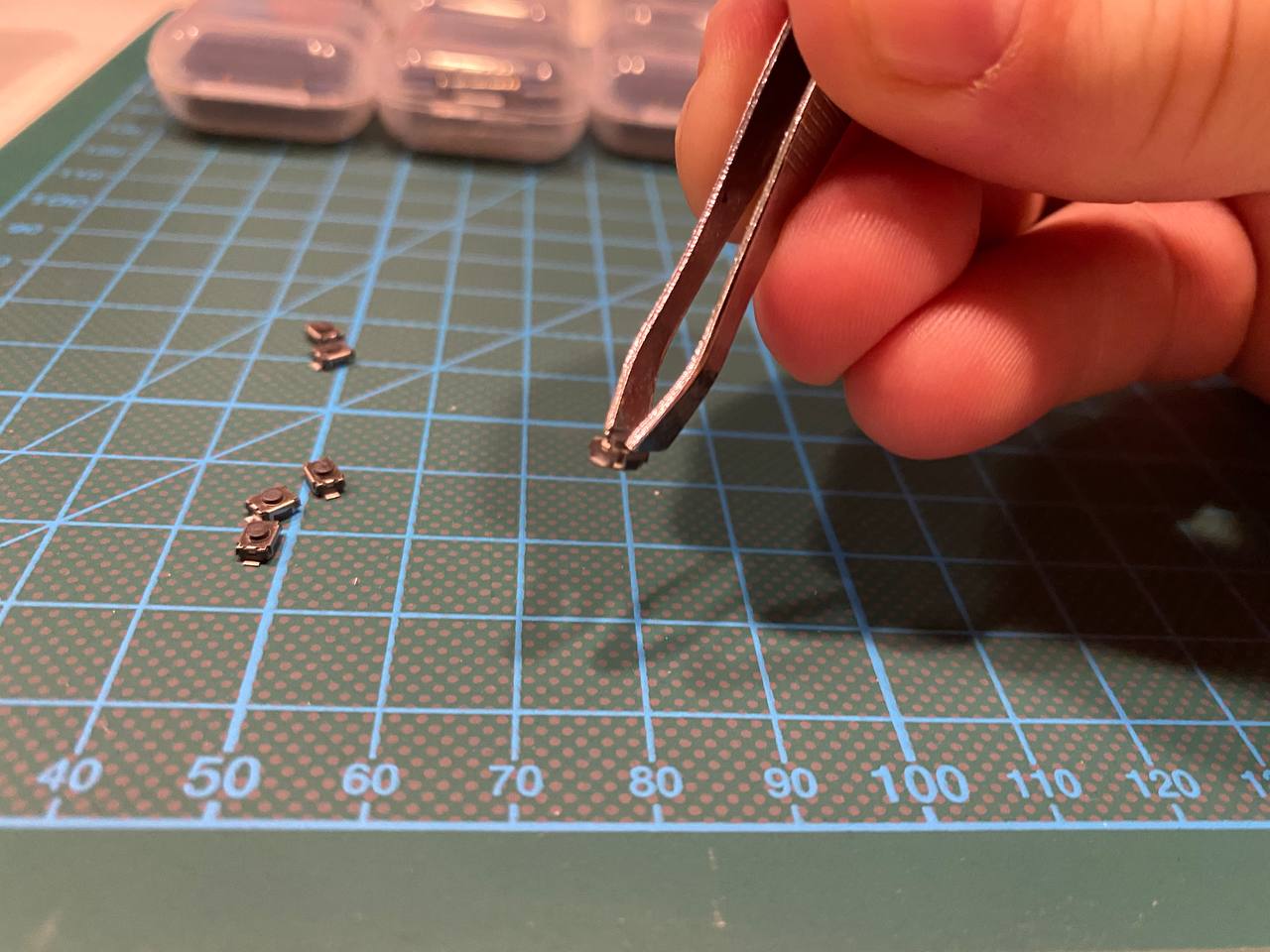
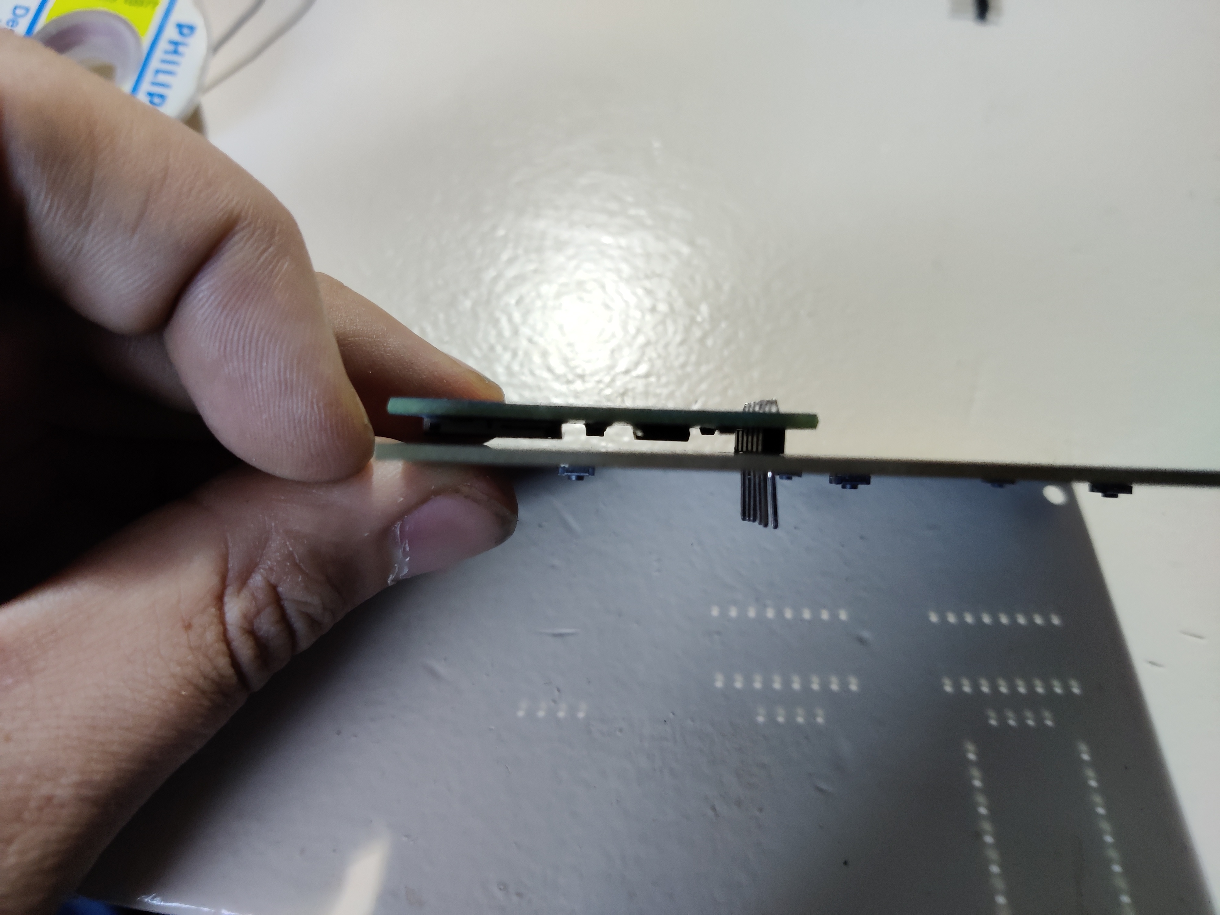
Grab the button with a pair of tweezers as shown below.
Now heat the pin of the button of the pad that you have pre-tinned. Onces its soldered on, solder the other pad.
Repeat this 6 times with all the buttons.
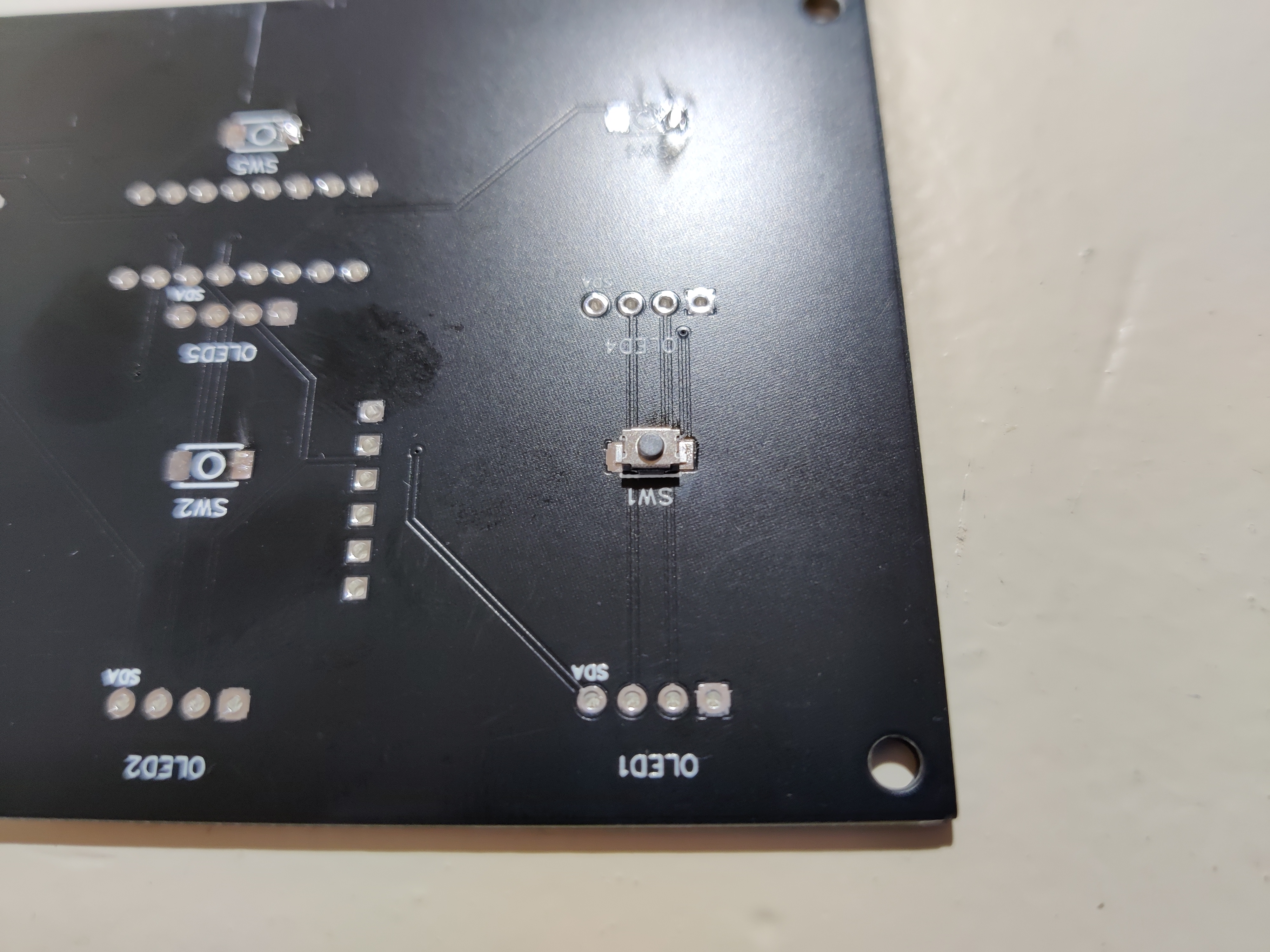
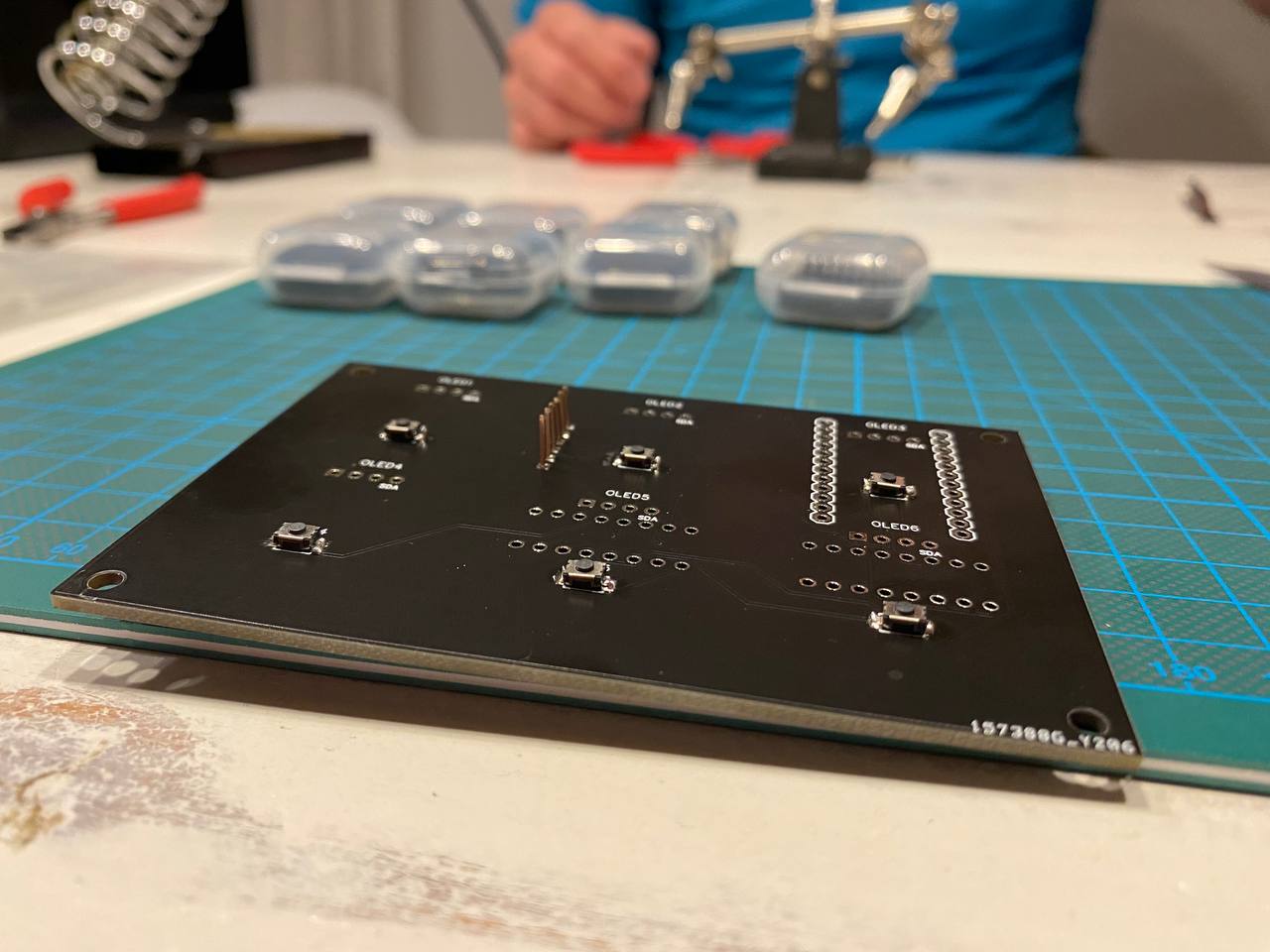
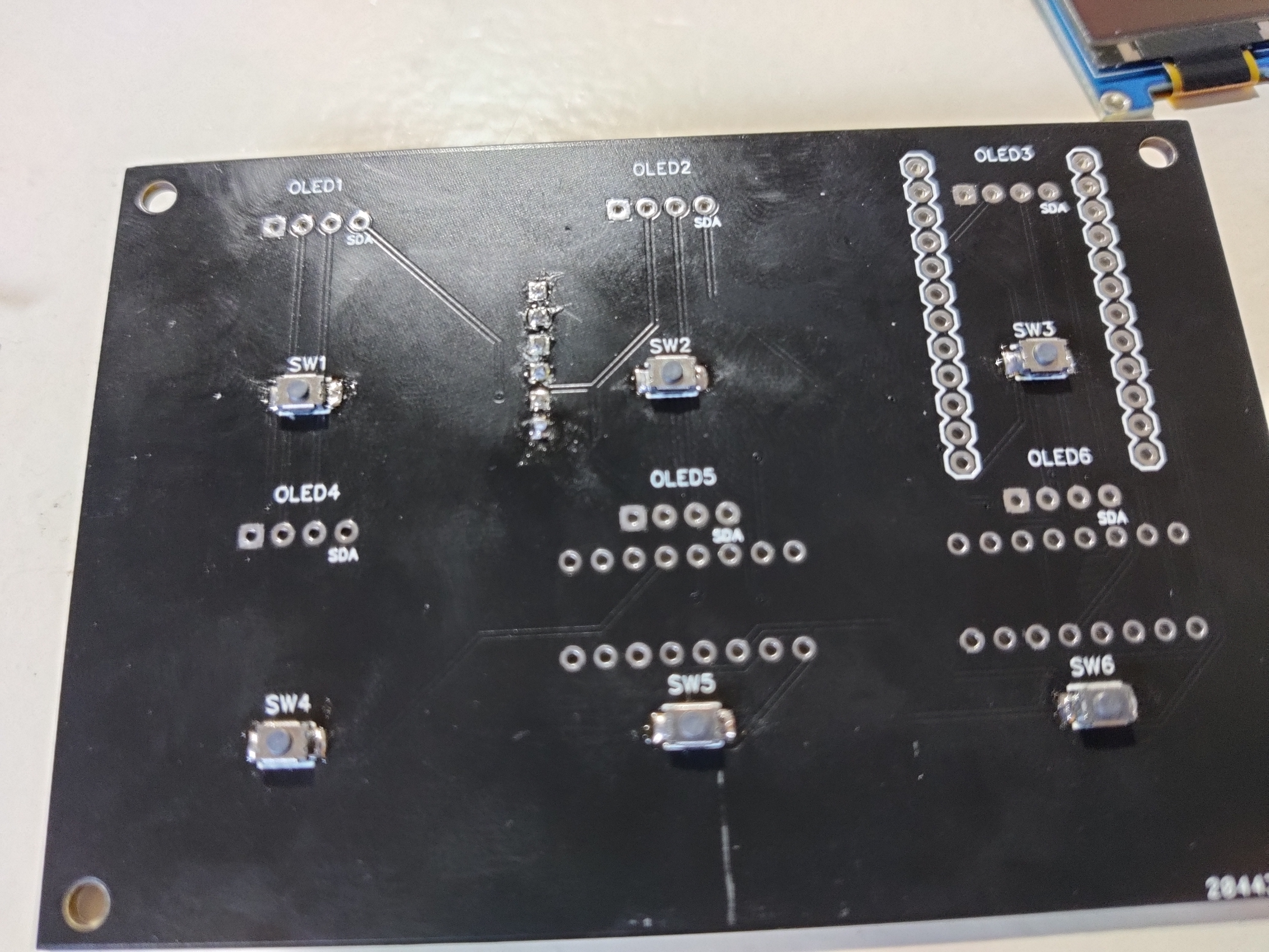
The result should look something like this.
Step 3: Solder the SD card reader
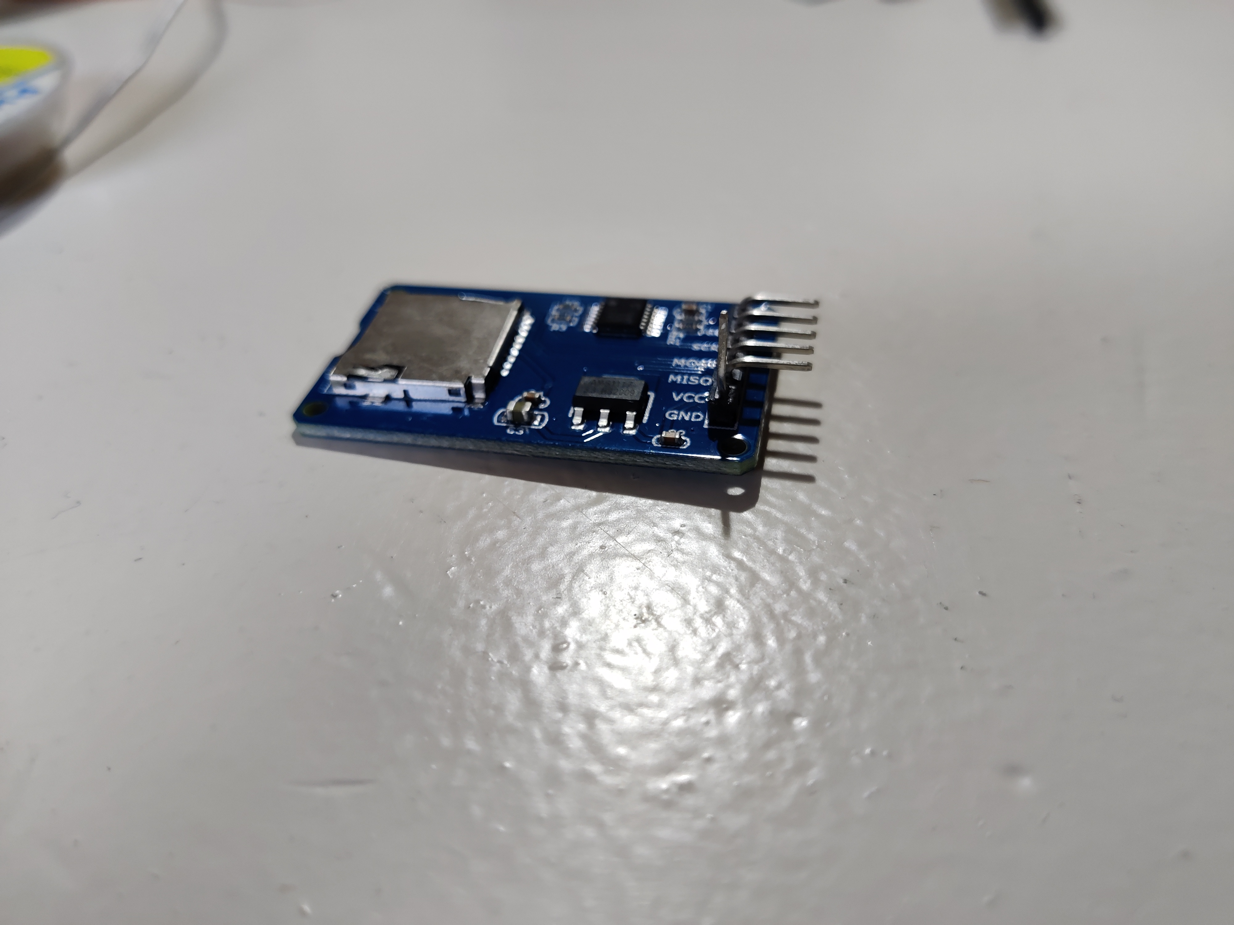
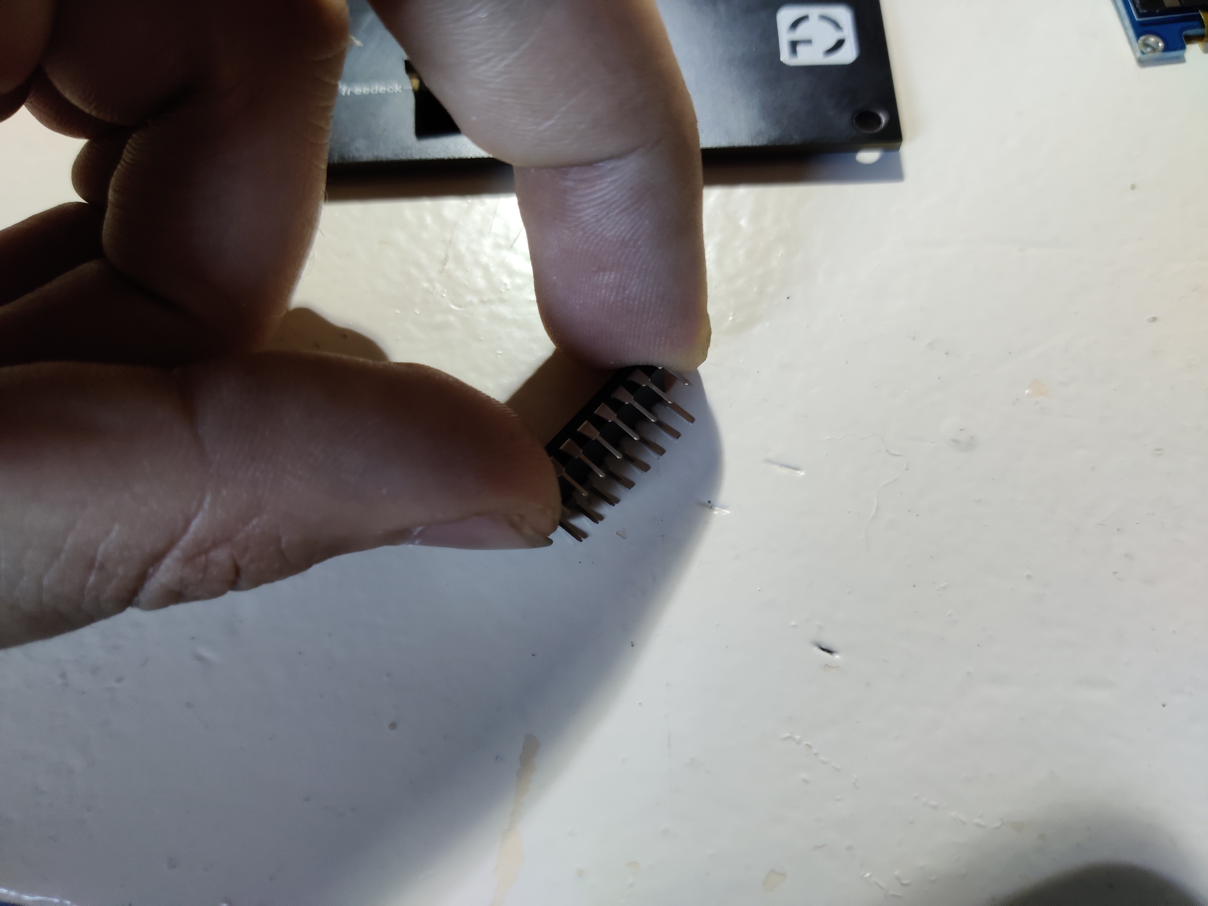
The SD card reader often comes with the headers bend 90 degrees.

For use on the freedeck you should bend them back so they fit easily on the PCB.
Grab a tool you seem fit for this, or use your hands to bend them
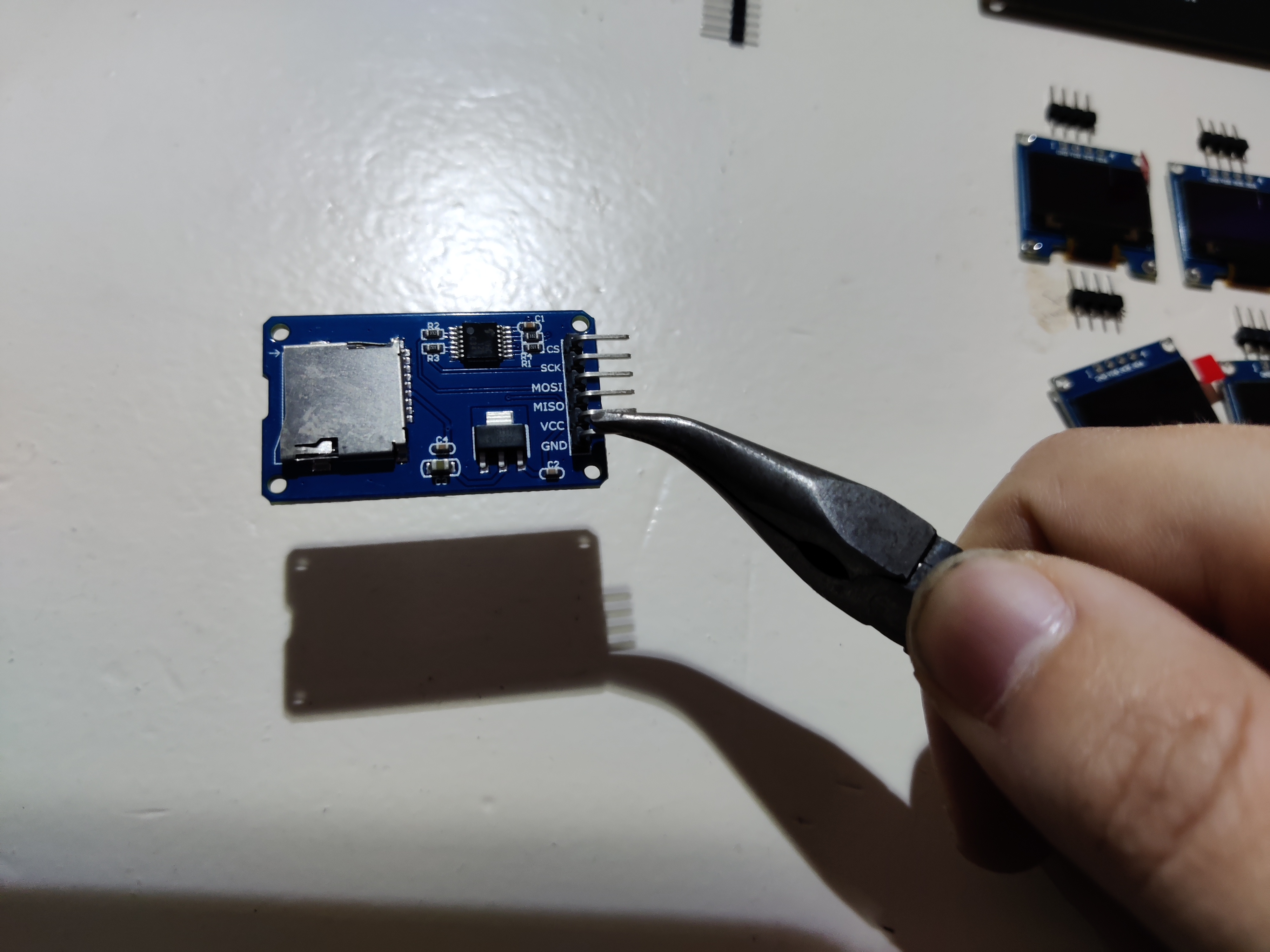
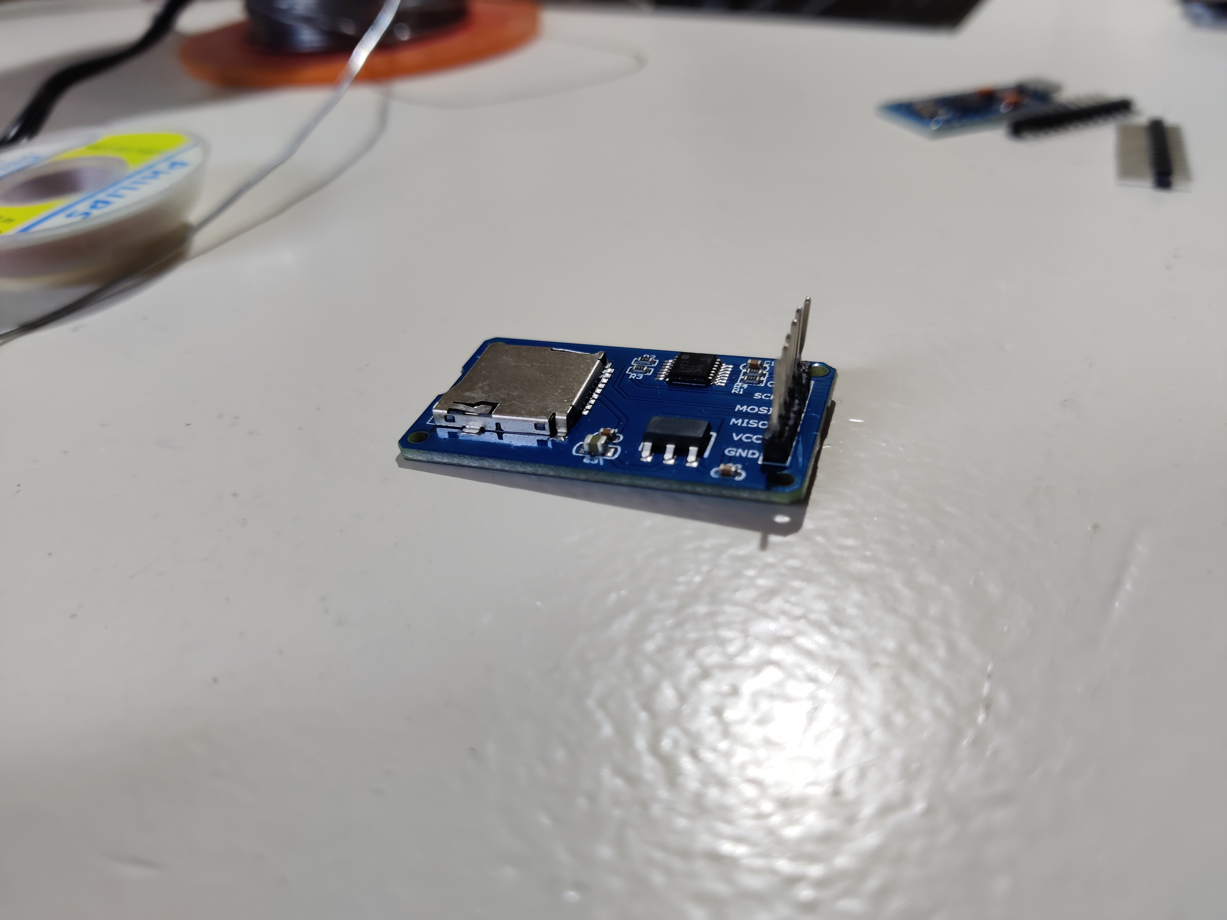
The reader should be on the side the buttons are not on, the pins should be on the size with the buttons
We advice to solder 1 pin. As shown below. this makes it so it can be adjusted to be paralell to the PCB (For the best result)
Heat the one soldered one to align it. Onces you're satisfied with the result, solder the rest. Do not use too much tin on those pins. The groundplane might be a bit harder to solder since it needs more time to warm up. Keep this in mind when soldering to give this pin some more time to flow.
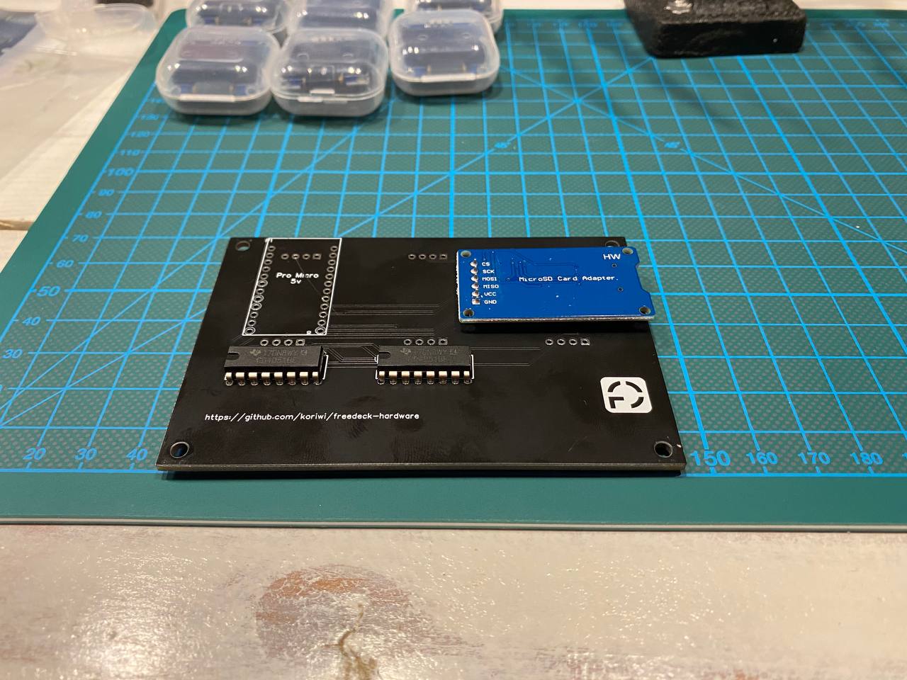
The result should look like this:
Cut the pins as close to the solder joints as possible. If you don't cut them you will have problems with the oleds later on.
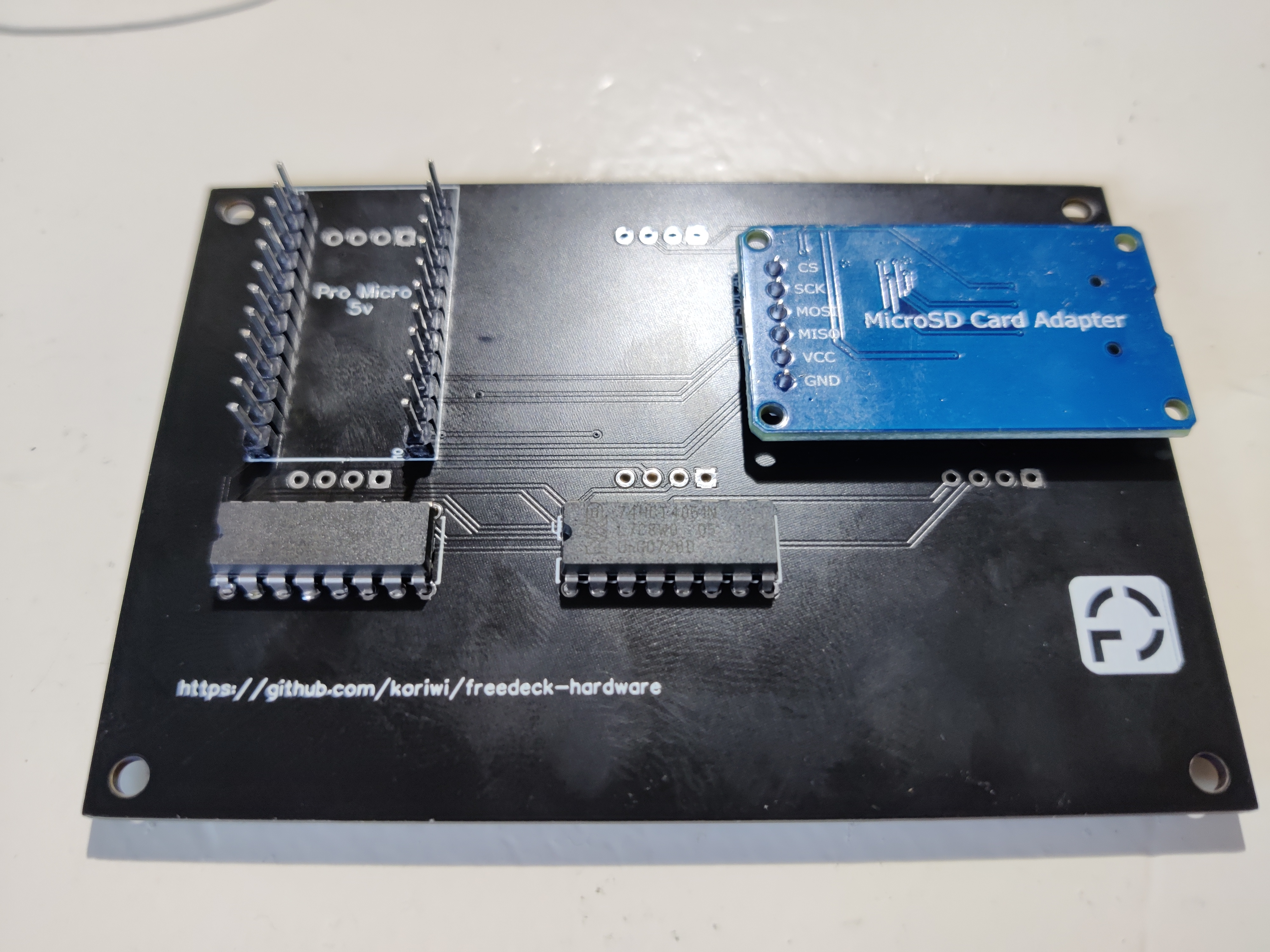
Step 4: Soldering the multiplexers
! WARNING for PI PICO check pcb markings for orientation
! The multiplexers are rotated 180° on the freedeck-pico compared to the freedeck-micro. (thx @IAmOrion)
(If you are uncertain about this step, you can also use IC-Sockets to solder, and mount the IC's in there)
The IC's should be soldered in the right orientation. If not, they wont work and you have the risk of blowing the multiplexers.
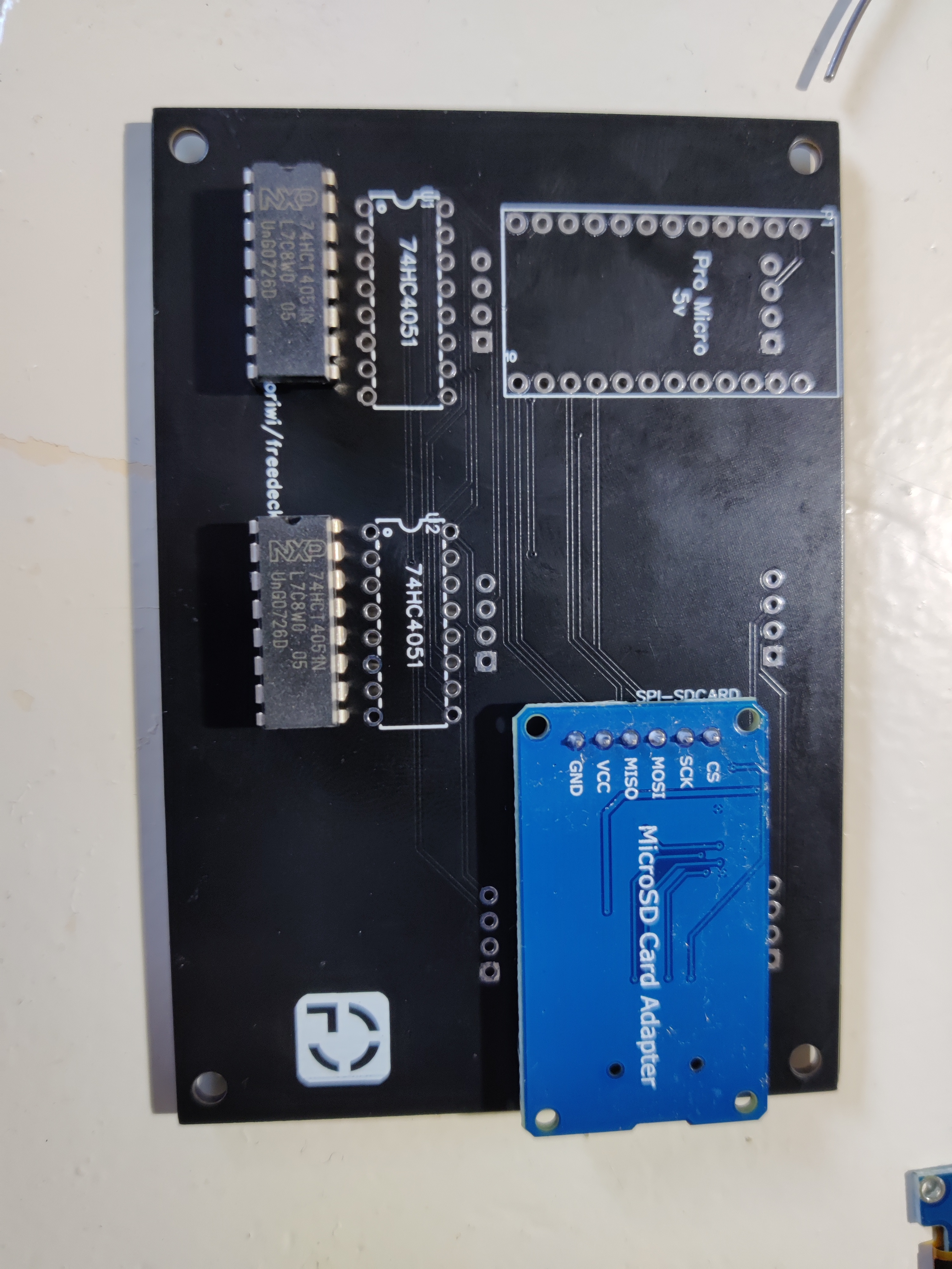 On the multiplexers there is a little cut out on one of the ends. This should correpond with the chipout on the PCB layout.
The IC won't fit directly into the footprint, you need to bend them carefully. My advice is to use a flat surface to bend them equally.
Carefully turn around the PCB, and solder the multiplexers. Solder the 2 opposite pins so you can easily adjust the IC to make it look good
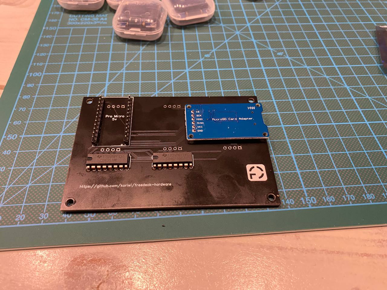
Cut the access parts of the pins. The result shoud look like this:
Step 5: Soldering the arduino headers
In step 5 we only solder the headers of the arduino to the PCB. Do not solder the arduino on to the PCB yet. Otherwise you can't solder the oleds in the next step.
Place the headers in the footprint
Then solder one pin on both headers and place the arduino on it. Make sure it fits, if not, adjust the pins.
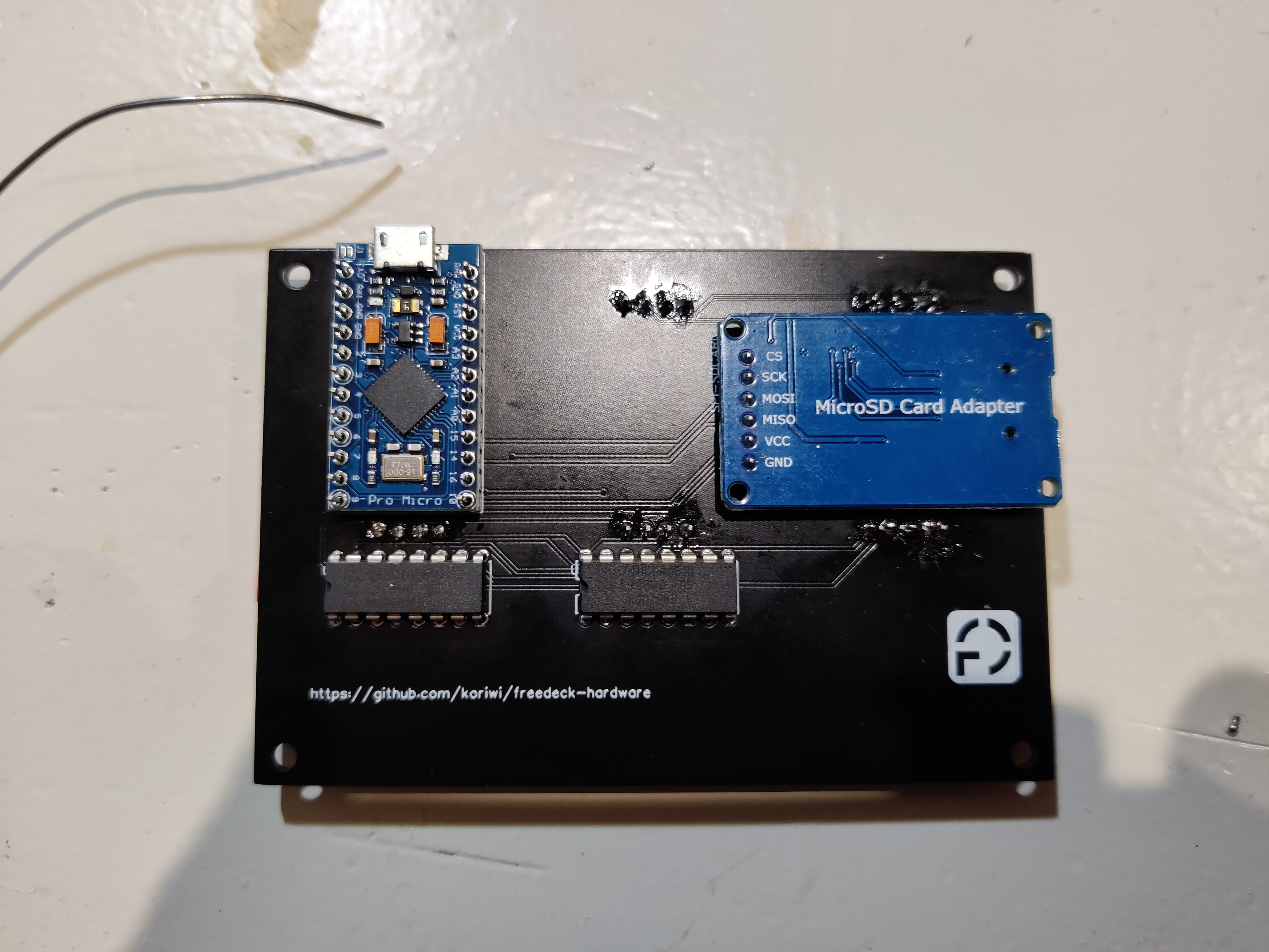
The result:
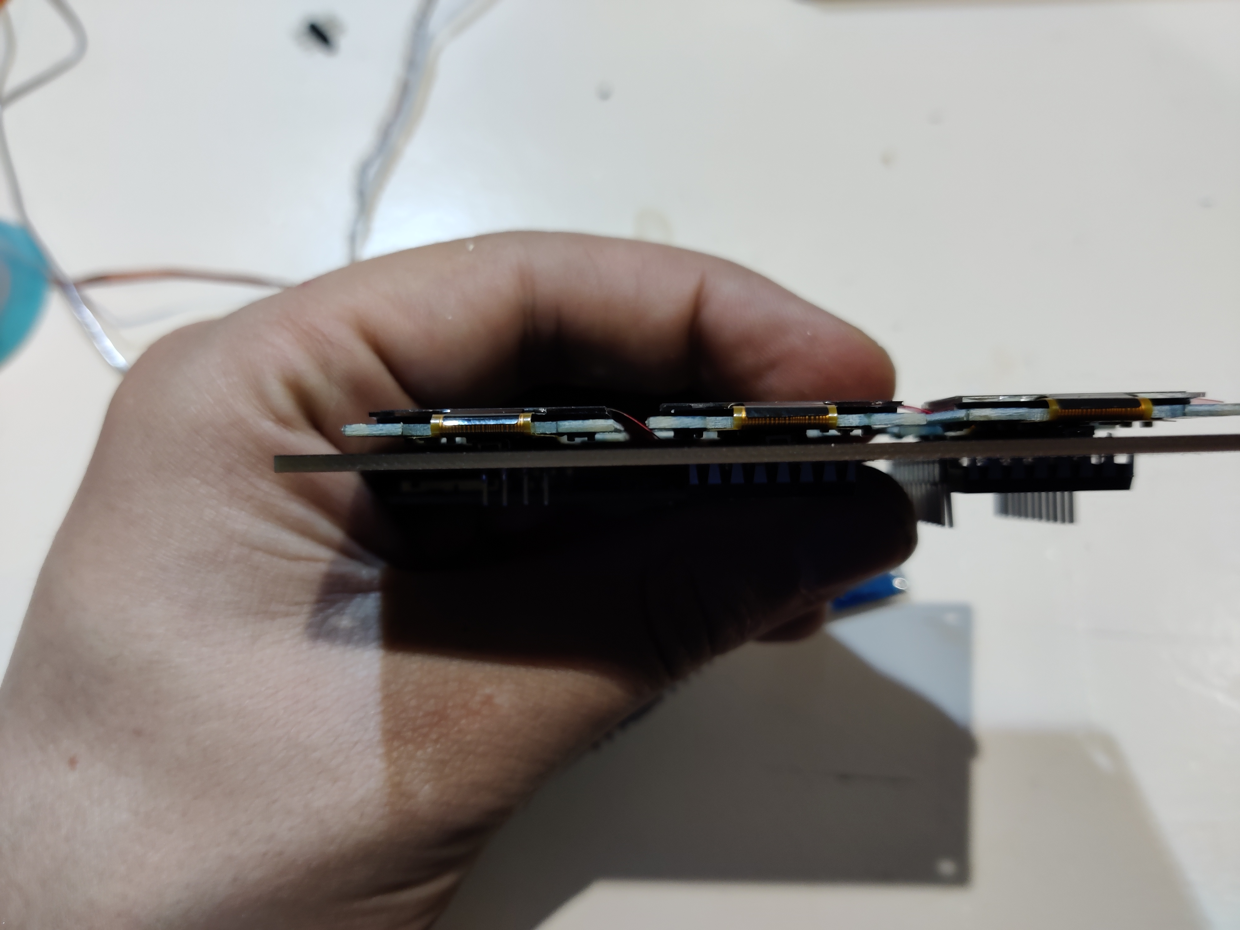
Step 6: Soldering the Oleds
If you want the freedeck enclosed with a self printed 3D enclosure, you should trim the header on top of the oleds so its flush with the top of the screen.
To solder them, do it one by one. Solder 1 pin of the connector, heat it, and adjust. The best result you can get is when they are all aligned nicely (also the best look inside of a enclosure).
Onces you're happy with it, solder the rest of the pins
Step 7: Soldering the arduino
Not that quick! Please check first for shorts! If there are any, resolve them first! A short will heat up the micro and can kill it. Be warned
After all the screens are soldered on, you can solder the arduino on to the headers.