How to use the interface - FontysAtWork/ESA-PROJ GitHub Wiki
Using the GUI
When you start the GUI only two things are possible. Loading in a map and YAML with the buttons, and connecting to the ROS master. After connecting to the ROS master the option to dynamically load an image is added. Before continuing with the GUI you need to load a map, either with the button or dynamically. After this has been done the rest of the GUI becomes available.
Loading map
There are two ways of showing the map into the GUI. This is always via a local image and data file. The method for importing the data is different though. The first way is using the buttons to load the image and YAML file into the GUI. The second way is starting the map_server with the image and YAML file and then getting the data from this server.
All data is gathered from the map_server or map_saver. More on that here.
Local image & data
Creating a local image and data file is done by using the map_saver. This is explained in the map_server page on the wiki.
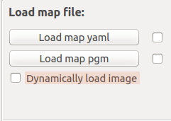
Loading in a map is done via the Load map file: section in the GUI. The first way to load the image is by using the two buttons in this section. If one of the two has been loaded the checkmark gets marked to show it has been done.
The second way to load the map is by clicking the Dynamically load image checkmark. This will start the timer to update the map every 3 seconds. The map_server has to have been started with an image to show.
These different ways are mutually exclusive and if one is selected the other one gets deselected.
The first button is Load map yaml. This button is used to load in the YAML file generated by the map_saver.
The second button is Load map pgm. This button is used to load in the pgm file generated by the map_saver.
The checkmark is Dynamically load image. This checkmark is used to indicate whether the map is loaded from the map_server.
Using the map
After you've loaded in a map it fills the left side of the GUI. There is a clickable overlay on the map and when clicked it calls a function to put the coordinates of the click in the marker and no go line section on the right.
When you add a marker to the list, the marker will show up in the desired spot. This is in green for the shelf markers, light blue for the workstation markers, pink for the conveyor markers, orange for the waypoint markers and in purple for the precision markers. The robot itself is shown in a blue color. The current position of the robot has a box around it to show the size of the robot, the angle that the robot is positioned in and a arrow to indicate the direction. When a marker is selected in the view on the left the marker associated with it turns red. It will also create a box around the marker that shows the size, angle and direction of the marker.
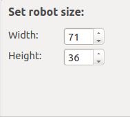
The size of the robot can be edited on the right side with the Set robot size section. Here you can alter the width and the length of the robot to be shown on the image.
Creating markers
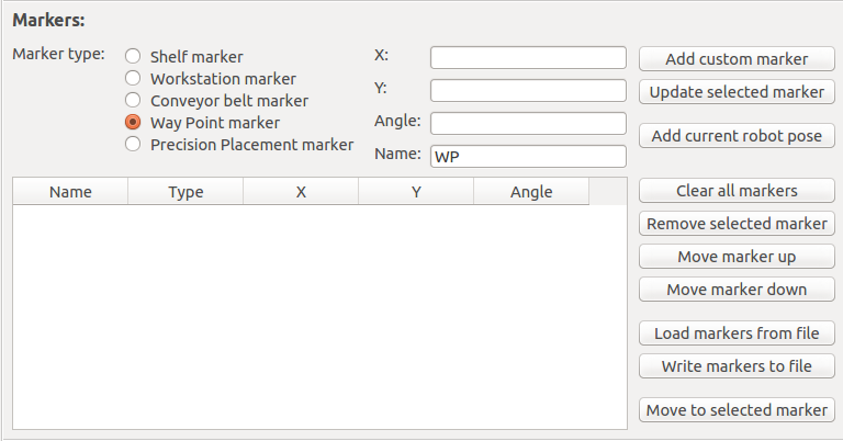
Markers are used by the robot to find certain specific points within the map. The markers consist of five attributes. A name, a type, X position on the map, Y position on the map and an angle. Creating a marker is done in the Markers section of the GUI.
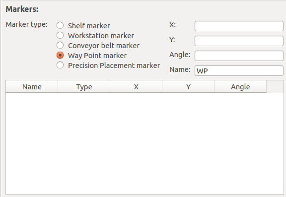
At the top left of the Marker section is the spot where the current information about the markers is shown. At the left side of this is the type of the marker shown and on the right side the other information. There are five types available as specified by the competition rules. The types are shelf, workstation, conveyor, waypoint and precision placement. The type of marker adds a prefix to the name of the marker.
At the right of the top left section is where the data of the markers are shown. When a new marker is selected these will reflect the data of the selected marker. The text in the four boxes is editable and can be configured for the marker of choice.
On the image portion of the GUI, the whole left side, there is an overlay that is clickable. When this overlay is clicked the X and Y position of the mouse, on the image portion, are gathered and put in the X and Y text boxes. These coordinates are still editable for the perfect position.
In the bottom of the left side is where you can view the list of the current markers. When selecting a new marker the details of the marker line shown in the top section. The marker is also selected in the image and it shows a box around the marker. This box is angled at the angle set within the marker and an arrow pointing in its direction.
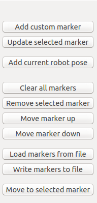
At the right section of the marker section are the buttons to interact with the markers. There are ten buttons in total.
The Add custom marker button is to add a marker that is completely custom. It gathers all the data from the fields in the left section and use this to create a new marker.
The Update selected marker button is for updating the currently selected marker. Any changes made to the marker will be saved to the marker and cannot be undone.
The Add current robot pose button is for adding the current robot pose as a marker. This will gather the type and name setting from the top setting. It will combine this with the robot position gathered from ROS and add it as a marker to the list.
The Clear all markers button will remove all of the markers in the list. This can not be undone and all the markers will be deleted permanently.
The Remove selected marker button will remove the currently selected marker from the list. This can not be undone and it will be deleted permanently.
The Move marker up button moves the currently selected marker up in the shown list. This is based on the shown list and not the list within the code itself.
The Move marker down button moves the currently selected marker down in the shown list. This is based on the shown list and not the list within the code itself.
The Load markers from file button opens up a browsing window. This lets you select a .yaml file which it then loads. It will parse this file and add any markers that it finds into the marker list.
The Write markers to file button opens up a browsing window. Here you can select a file to write the markers into or create a new file to write the markers into. After selecting a file it writes all of the markers in the list to the file. This will clear the whole file and no original data will be left.
The Move to selected marker gets the selected marker and send the position of this marker over ROS to the robot. The robot will then move to this position.
Creating no-go zones
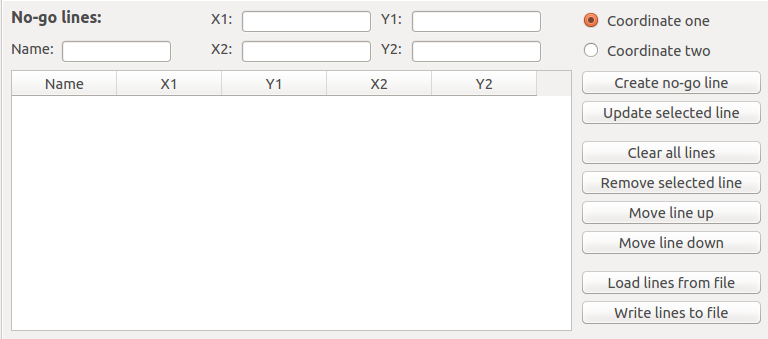
No go lines are used by the robot to avoid certain areas. These lines consist of two point on the map and a line will be drawn between these two points, the robot will not pass this line. If a box or other form is created the robot will not go inside of the box.
At the top left of the NoGoLines section is the spot where the current information about the line is shown. This shows the x and y coordinates of the two points and the name of the line.
On the image portion of the gui, the whole left side, there is an overlay that is clickable. When this overlay is clicked the X and Y position of the mouse, on the image portion, are gathered and put in the X and Y text boxes. Which textbox it is put in depends on which of the two radiobuttons on the right are selected. These coordinates are still editable for the perfect position.
In the bottom of the left side is where you can view the list of the current lines. When selecting a new line the details of the line is shown in the top section.

At the right section of the marker section are the buttons and radiobuttons to interact with the lines. There are eight buttons in total and two radiobuttons.
The Create no-go line button is to add a line that is completely custom. It gathers all the data from the fields in the top section and use this to create a new line.
The Update selected line button is for updating the currently selected line. Any changes made to the line will be saved to the line and cannot be undone.
The Clear all lines button will remove all of the lines in the list. This can not be undone and all the lines will be deleted permanently.
The Remove selected line button will remove the currently selected line from the list. This can not be undone and it will be deleted permanently.
The Move line up button moves the currently selected line up in the shown list. This is based on the shown list and not the list within the code itself.
The Move line down button moves the currently selected line down in the shown list. This is based on the shown list and not the list within the code itself.
The Load lines from file button opens up a browsing window. This lets you select a .yaml file which it then loads. It will parse this file and add any lines that it finds into the line list.
The Write lines to file button opens up a browsing window. Here you can select a file to write the lines into or create a new file to write the lines into. After selecting a file it writes all of the lines in the list to the file. This will clear the whole file and no original data will be left.
Porting information to the robot
The information that is given to the robot by using the map_marker is the markers and the no go lines. Both of these can be made from within the gui and exported to files. The markers have to be written to files and these should then be loaded into the competition portion of the robot to be usable. The no go lines are saved in an occupancy grid in the node that is made for this. From this node an image can be exported through the map_saver. This can then be started with the map_server and serves the robot during competition.
Connecting to ROS core
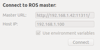
Connecting to a ROS master is required to start the rest of the GUI. This section of the GUI is used to connect the GUI to the ROS master that is running. There are two ways to connect to a ROS master, either with the environment variables set in ROS or with a master URL and host IP. Standard the environment variables are used and the textboxes are disabled. When the checkmark is deselected the option to use the remote ROS master becomes available.
The Connect button uses the current settings of either using environment variables or the specified master and host to connect to the ROS master and initialize the ROS portion of the GUI.
Panic button
The UI provides a software emergency stop button when something goes wrong.
In short this stops the robot movement by killing movement messages to the wheels. For more information see the Panic node page.