templates - FengtianGu/Sonoff-Tasmota GitHub Wiki
Starting with Tasmota version 6.5, devices can be configured by users using a Template.
These are intended to be an easy way for users to create and share configurations for devices that are unsupported in Tasmota but have common characteristics with existing modules. We encourage everyone who creates a template for a new unknown device to add it to the database with an image of the device, links to the manufacturer or where it can be found and, of course, the template for it.
To provide easy processing by Tasmota, a user template is written as a JSON text and could look like this:
{"NAME":"UserModule1","GPIO":[17,148,29,149,7,255,255,255,138,255,139,255,255],"FLAG":0,"BASE":18}
More about template properties at the bottom of the article.
Go to Configuration - Configure Template ...
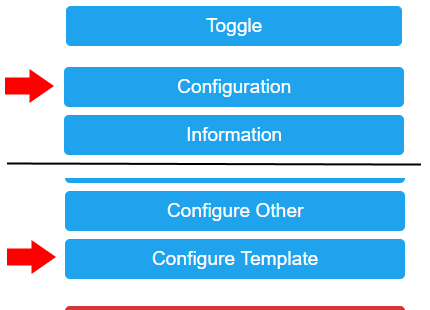
... and you'll end up looking at this screen.

Time to create your template.

- Change the template name (also defines the name for
Module 0). - Select a module to BASE your template on. If you're not sure,
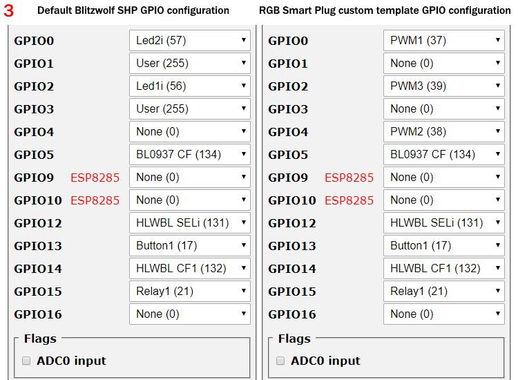
Module 18is the best choice. In this example the device is based on Blitzwolf SHP (45) module. - Configure the GPIOs to match your device. If you do not know what pins your device uses, employ the new device configuration procedure to determine the correct pin assignments.
- Click on Save.

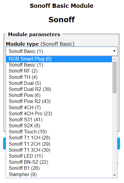
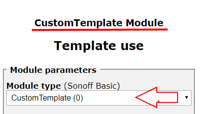
- Select
Module 0in Configuration - Configure Module.
In the example dropdown menu you see the template name that is defined in step 1 (in this case RGB Smart Plug) always followed by (0).
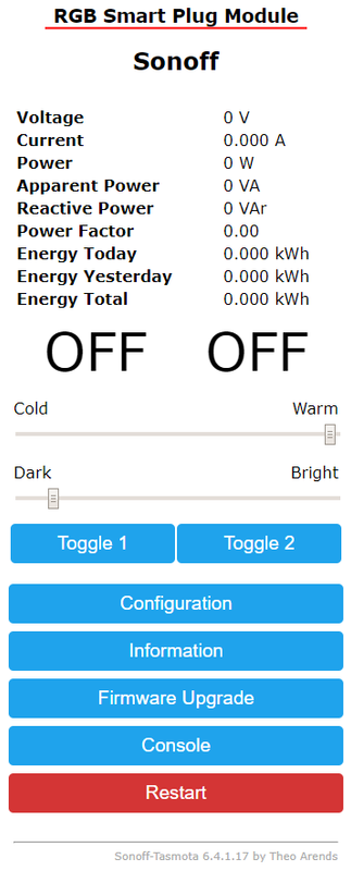
After clicking Save, your device will reboot with the new settings.
Now that you've set up your previously unsupported device in Tasmota it is time to share the knowledge:
- Check that
Module 0is selected in the Configuration - Configure Module menu. - Open up Console and issue command
Templatewhich will output a string with the configuration of your currently active template. Our example gives the following:
MQT: stat/sonoff/RESULT = {"NAME":"RGB Smart Plug","GPIO":[37,0,39,0,38,134,0,0,131,17,132,21,0],"FLAG":0,"BASE":45}
Copy the string {"NAME":"RGB Smart Plug","GPIO":[37,0,39,0,38,134,0,0,131,17,132,21,0],"FLAG":0,"BASE":45} and share it on our device repository page.
You can set up your device in module Configuration - Configure Module and use command Template 255 to merge the settings from Configure Module with current template into a new Template named "Merged".
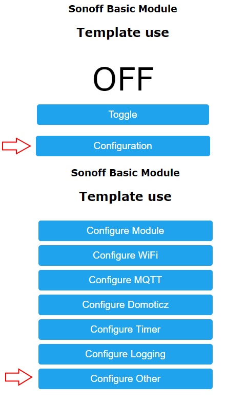
Go to Configuration - Configure Other
When there:
- Paste your template into the Template field
- Make sure you check Activate
- Click on Save.
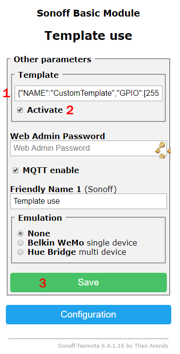
The device will reboot with a name reflecting your template name and Module 0 selected which has your new template stored.
A user provided template can be stored in Sonoff-Tasmota using the Template command. It has the following parameters.
| Parameter | Description |
|---|---|
|
Show current Template |
0 |
Create template from active module |
1..69 |
Create template from a supported module |
{ ... } |
Store template written in a JSON string |
Template {"NAME":"UserModule1","GPIO":[17,148,29,149,7,255,255,255,138,255,139,255,255],"FLAG":0,"BASE":18} stores a complete template based on the Generic module
Template {"NAME":"AnotherModuleName"} updates the name of a stored template
Template {"FLAG":1} updates the flag of a stored template
Template {"BASE":0} updates the base of a stored template to Generic
After setting a template in command line it is necessary to issue Module 0 command if the device doesn't reboot on its own.
Let's look again at our example template
{"NAME":"UserModule1","GPIO":[17,148,29,149,7,255,255,255,138,255,139,255,255],"FLAG":0,"BASE":18}
The four properties with UPPERCASE property names have the following functionality:
| Property name | Property value description |
|---|---|
| NAME | Up to 14 characters for the Module name |
| GPIO | Up to 13 decimal numbers from 0 to 255 representing GPIO0 to GPIO5, GPIO09, GPIO10 and GPIO12 to GPIO16 |
| FLAG | 8 bit mask flag register |
| BASE | Module number of a hard-coded device to be used when device specific functionality is needed |
GPIO# |00| 01|02| 03|04| 05| 09| 10| 12| 13| 14| 15| 16|
CODE  [17,148,29,149,52,255,255,255,138,255,139,255,255]
The GPIO functionality numbers are the same as shown by command GPIOs. In addition code 255 is added to select a GPIO as user configurable via the GUI Configure Module menu.
example
In our example GPIO00 has the number
17which corresponds to Button1 according to the following table. If you change that to9in your template it would then become a Switch1.
| # | Function | # | Function | # | Function | # | Function |
|---|---|---|---|---|---|---|---|
| 0 | None | 255 | User define | ||||
| 17 | Button1 | 18 | Button2 | 19 | Button3 | 20 | Button4 |
| 90 | Button1n | 91 | Button2n | 92 | Button3n | 93 | Button4n |
| 9 | Switch1 | 10 | Switch2 | 11 | Switch3 | 12 | Switch4 |
| 13 | Switch5 | 14 | Switch6 | 15 | Switch7 | 16 | Switch8 |
| 82 | Switch1n | 83 | Switch2n | 84 | Switch3n | 85 | Switch4n |
| 86 | Switch5n | 87 | Switch6n | 88 | Switch7n | 89 | Switch8n |
| 21 | Relay1 | 22 | Relay2 | 23 | Relay3 | 24 | Relay4 |
| 25 | Relay5 | 26 | Relay6 | 27 | Relay7 | 28 | Relay8 |
| 29 | Relay1i | 30 | Relay2i | 31 | Relay3i | 32 | Relay4i |
| 33 | Relay5i | 34 | Relay6i | 35 | Relay7i | 36 | Relay8i |
| 52 | Led1 | 53 | Led2 | 54 | Led3 | 55 | Led4 |
| 56 | Led1i | 57 | Led2i | 58 | Led3i | 59 | Led4i |
| 157 | LedLink | 158 | LedLinki | ||||
| 37 | PWM1 | 38 | PWM2 | 39 | PWM3 | 40 | PWM4 |
| 41 | PWM5 | 46 | PWM1i | 47 | PWM2i | 48 | PWM3i |
| 49 | PWM4i | 50 | PWM5i | ||||
| 42 | Counter1 | 43 | Counter2 | 44 | Counter3 | 45 | Counter4 |
| 94 | Counter1n | 95 | Counter2n | 96 | Counter3n | 97 | Counter4n |
| 150 | Rotary1a | 151 | Rotary1b | 152 | Rotary2a | 153 | Rotary2b |
| # | Function | # | Function | # | Function |
|---|---|---|---|---|---|
| 1 | DHT11 | 2 | AM2301 | 3 | SI7021 |
| 5 | I2C SCL | 6 | I2C SDA | ||
| 7 | WS2812 | ||||
| 8 | IRsend | 51 | IRrecv | ||
| 60 | MHZ Tx | 61 | MHZ Rx | ||
| 64 | SAir Tx | 65 | SAir Rx | ||
| 62 | PZEM0XX Tx | 63 | PZEM004 Rx | ||
| 98 | PZEM016 Rx | 99 | PZEM017 Rx | ||
| 69 | PMS5003 | ||||
| 71 | SerBr Tx | 72 | SerBr Rx | ||
| 73 | SR04 Tri | 74 | SR04 Ech | ||
| 101 | SDS0X1 Tx | 70 | SDS0X1 Rx | ||
| 102 | HX711 SCK | 103 | HX711 DAT | ||
| 104 | TX20 | ||||
| 105 | RFSend | 106 | RFrecv | ||
| 107 | Tuya Tx | 108 | Tuya Rx | ||
| 109 | MGC3130 Xfr | 110 | MGC3130 Rst | ||
| 111 | SSPI MISO | 112 | SSPI MOSI | 113 | SSPI SCLK |
| 114 | SSPI CS | 115 | SSPI DC | 116 | RF Sensor |
| 117 | AZ Rx | 118 | AZ Tx | ||
| 119 | MX31855 CS | 120 | MX31855 CLK | 121 | MX31855 DO |
| 130 | HLWBL SEL | 131 | HLWBL SELi | 132 | HLWBL CF1 |
| 133 | HLW8012 CF | 134 | BL0937 CF | ||
| 135 | MCP39F5 Tx | 136 | MCP39F5 Rx | 137 | MCP39F5 Rst |
| 138 | PN532 Tx | 139 | PN532 Rx | ||
| 140 | SM16716 CLK | 141 | SM16716 DAT | 142 | SM16716 PWR |
| 143 | MY92x1 DI | 144 | MY92x1 DCKI | ||
| 145 | CSE7766 Tx | 146 | CSE7766 Rx | ||
| 147 | ALux IrRcv | 159 | ALux IrSel | ||
| 148 | Serial Tx | 149 | Serial Rx |
Google Sheet with the GPIOS sorted by number or alphabetically.
The FLAG value is an 8-bit mask where each bit controls a feature. Add FLAG values to set multiple bits.
| FLAG | Mask | Feature description |
|---|---|---|
| 0 | xxxxxxxx | No features |
| 1 | xxxxxxx1 | Use Analog0 (ADC0) as an input if USE_ADC_VCC, defined in my_user_config.h, is disabledSelecting ADC0 allows input of an analog signal through the ADC0 (A.K.A. A0) ESP8266 input (pin 6). ADC0 will be reported in telemetry messages as well as in the web UI. It can also be used as a trigger in rules. Check your Wi-Fi module. The ESP8266 A0 pin supports a maximum voltage of 1.0V. Many newer Wi-Fi modules have an on-board voltage divider to support a higher A0 input voltage range (typically in the range between 0 and 3.3 volts). You may need to use a an external voltage divider to ensure your input voltage is in the right range. |
| 2 | xxxxxx1x | Allow ADC0 as Temperature sensor when define USE_ADC_VCC is disabled. Introduced in 6.5.0.9 |
| 4 | xxxxx1xx | Not used |
| 8 | xxxx1xxx | Not used |
| 16 | xxx1xxxx | Not used |
| 32 | xx1xxxxx | Not used |
| 64 | x1xxxxxx | Not used |
| 128 | 1xxxxxxx | Not used |
BASE is the starting module setup for the custom template. Some modules, not all, include special programming. If your device is similar to an existing built-in module it is best to use that as a starting point. When you're not sure which BASE module is suitable for your device use the Generic (18) module.
example
In the RGB Smart Plug template we used the
BlitzWolf SHP (45)module as BASE since the power monitoring circuitry is identical but GPIO00, GPIO02 were changed and an unused GPIO04 was added to enable the RGB LED function. Using that specific module we took advantage of that module's calibrated power monitoring special programming which theGeneric (18)module does not use.
The following table lists hard-coded device specific functionality.
| BASE | Module | Description |
|---|---|---|
| 1 | Sonoff Basic | |
| 2 | Sonoff RF | |
| 3 | Sonoff SV | |
| 4 | Sonoff TH | |
| 5 | Sonoff Dual | Process relay and button via hardware serial interface using GPIO01 and GPIO03. Change baudrate to 19200 bps. Process buttons as single press only |
| 6 | Sonoff POW | |
| 7 | Sonoff 4Ch | |
| 8 | Sonoff S2X | |
| 9 | Slampher | |
| 10 | Sonoff Touch | Invert LedState 1 functionality |
| 11 | Sonoff LED | Set light type to 2 PWM channels disregarding SetOption15. Fix device specific LED instabilities by disabling GPIO04, GPIO5 and GPIO14 |
| 12 | 1 Channel | |
| 13 | 4 Channel | See Sonoff Dual |
| 14 | Motor C/AC | Force all relays ON at Power On and disable command PowerOnState |
| 15 | ElectroDragon | |
| 16 | EXS Relay(s) | Enable pulse latching using even/odd numbered relay pairs |
| 17 | WION | |
| 18 | Generic | Show Wemos specific pin information in GUI |
| 19 | Sonoff Dev | |
| 20 | H801 | Change hardware UART Tx from GPIO01 to GPIO02 |
| 21 | Sonoff SC | Enable and Process data via hardware serial interface using GPIO01 and GPIO03. Change baudrate to 19200 bps |
| 22 | Sonoff BN-SZ | Set light type to 1 PWM channel disregarding SetOption15 |
| 23 | Sonoff 4Ch Pro | Button handling disregarding SetOption13 only allowing single press to enable RF learning while holding the button |
| 24 | Huafan SS | |
| 25 | Sonoff Bridge | Enable and Process data via hardware serial interface using GPIO01 and GPIO03. Change baudrate to 19200 bps. Process 16 buttons in web GUI. Enable EFM8BB1 firmware upload |
| 26 | Sonoff B1 | Set light type to RGBWC using MY92x1 |
| 27 | Ailight | Set light type to RGBW using MY92x1 |
| 28 | Sonoff T1 1Ch | See Sonoff Touch |
| 29 | Sonoff T1 2Ch | See Sonoff Touch |
| 30 | Sonoff T1 3Ch | See Sonoff Touch |
| 31 | Supla Espablo | |
| 32 | Witty Cloud | |
| 33 | Yunshan Relay | |
| 34 | MagicHome | |
| 35 | Luani HVIO | |
| 36 | KMC 70011 | |
| 37 | Arilux LC01 | |
| 38 | Arilux LC11 | |
| 39 | Sonoff Dual R2 | Process buttons as single press only |
| 40 | Arilux LC06 | |
| 41 | Sonoff S31 | Selects GPIO types for the CSE7766 (serial connected energy monitoring chip) with Rx and Tx hardware serial (even parity) on GPIO01 and GPIO03 respectively. Sets serial interface to 4800 baud and disables serial logging |
| 42 | Zengge WF017 | |
| 43 | Sonoff Pow R2 | |
| 44 | Sonoff IFan02 | Enable command Fanspeed. Disable Interlock and PulseTime. Tune status information, MQTT data and GUI. Sync with microcontroller. Process Domoticz Fan state |
| 45 | Blitzwolf SHP | Module specific power monitoring calibration |
| 46 | Shelly 1 | |
| 47 | Shelly 2 | |
| 48 | Xiaomi Philips | Process Color Temperature using PWM2 and Intensity using PWM1 |
| 49 | Neo Coolcam | |
| 50 | ESP SwitCh | |
| 51 | Obi Socket | |
| 52 | Teckin | |
| 53 | APLIC WDP303075 | |
| 54 | Tuya Dimmer | Enable and Process data via software or hardware serial interface using GPIO 148 and 149 or forced GPIO01 and GPIO03. Change baudrate to 9600 bps. Process all Buttons |
| 55 | Gosund SP1 v23 | |
| 56 | Armtronix Dimmers | Enable and Process data via software or hardware serial interface using GPIO 148 and 149. Change baudrate to 115200 bps. |
| 57 | SK03 Outdoor (Tuya) | |
| 58 | PS-16-DZ | Enable and Process data via software or hardware serial interface using GPIO 148 and 149. Change baudrate to 19200 bps. |
| 59 | Teckin US | |
| 60 | Manzoku Strip (EU 4) | |
| 61 | Obi Socket 2 | |
| 62 | YTF LR Bridge | Disable serial interface to stop loopback |
| 63 | Digoo DG-SP202 | |
| 64 | KA10 | |
| 65 | Luminea ZX2820 | |
| 66 | Mi Desk Lamp | Process rotary and Button1 data specific to this device |
| 67 | SP10 | |
| 68 | WAGA CHCZ02MB | |
| 69 | SYF05 |