Hardware Preparation - FengtianGu/Sonoff-Tasmota GitHub Wiki
You've followed Prerequisites and got everything you need. Now you have to prepare your device for flashing.
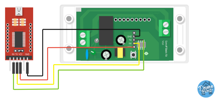
We need to connect to the serial programming interface of the ESP8266 chip. This is done by connecting our serial-to-USB converter TX and RX pins to the ESP8266 RX and TX pins and powering the chip with the 3.3V and GND pins.
In most cases those pins are available on the PCB in the form of pin holes or solder pads but pin headers or jumper wires need to be soldered or otherwise applied. In some cases you will need to solder wires directly on the chip's pins which requires some experience and good soldering equipment.
DO NOT CONNECT DEVICES TO MAINS POWER WHILE THE COVER IS OPEN AND CIRCUIT BOARD IS EXPOSED!!!
NEVER TRY TO FLASH WHILE YOUR DEVICE IS CONNECTED TO MAINS POWER!!!

YOU CAN BE ELECTROCUTED IF YOU DON'T KNOW WHAT YOU ARE DOING!
If you are not careful, your own health will be in danger. Shorting your serial interface with AC will fry your module and programmer and will also harm or destroy your computer. It is important to always have all mains power cables disconnected from the device while being connected via serial or even while the case of the module is opened.
Each device has its pins labelled differently. If the labelling isn't visible on the PCB please refer to the devices wiki entry or search the internet for correct pin locations. Device specific instructions and restrictions are documented in Device Templates Repository
When you have identified pins on your device, connect wires according to the table:
| Serial adapter | ESP8266 device |
|---|---|
| 3V3 | 3V3 or VCC |
| TX | RX |
| RX | TX |
| GND | GND |
Note that TX from your adapter goes to RX on the ESP8266 device and RX from adapter goes to TX on the device!
 ESP8266 needs to be put into Flash Mode before the firmware can be uploaded. This is done by pulling the GPIO0 pin to GND while the chip is booting.
On most devices the installed control button is connected to GPIO0 and GND, making entering Flash Mode very easy. On others you will need to short the pins on the PCB or directly on the chip with a jumper wire. Device specific instructions are documented in Device Templates Repository.
To bring ESP8266 into Flash Mode:
- Disconnect serial-to-USB adapter and power
- Connect GPIO0 and GND (by pressing the on-board button or connection with a wire)
- Connect the serial-to-USB adapter to your computer
- After a few seconds disconnect GPIO0 from GND (release button or break wire connection)
If everything went well, you are now in Flash Mode and ready to continue with flashing. If the flashing process is unable to start, disconnect the module and retry the steps.
- Double check the wire connections and soldering job for overflow
- Releasing GPIO0 button/wire before booting is finished
- Insufficient power delivered over the serial-to-USB adapter can prevent flashing. Supply more power with an additional 3.3V power supply or get an adapter with a better power supply.
- Not switching RX and TX pins
- Recheck your serial-to-USB adapter so it supplies 3.3V power instead of 5V