Lab 03 - IRL-CT/Developing-and-Designing-Interactive-Devices GitHub Wiki
-
Read through the lab below
-
DESIGN READING:
-
Paper prototyping is used by UX designers to quickly develop interface ideas and run them by people before any programming occurs.
-
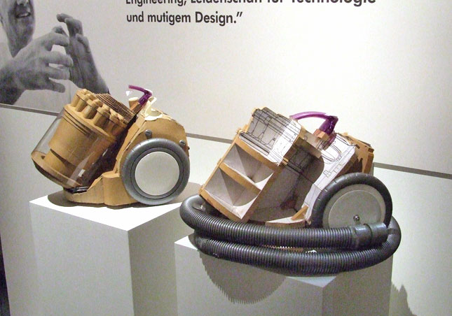
Cardboard prototypes help interactive product designers to work through additional issues, like how big something should be, how it could be carried, where it would sit.
-
Surprisingly complicated forms can be built with paper, cardstock or cardboard. The most advanced and challenging prototypes to prototype with paper are cardboard mechanisms which move and change.
- ELECTRONICS READING:
-
Scherz, Ch 15.1-15.4 Motors
-
How to pick the right battery for your project from Adafruit
- Check out some of the things in your kit that we'll be using this week:
| Part | What it's for | How to use it |
|---|---|---|
| 9V battery | Power the Arduino without USB | Attach it to the 9V battery connector |
| 9v battery connector | " " | Put the red wire in Vin, and the black line in GND |
| IDC connectors & ribbon cable | Breaking components off the circuitboard | insert ribbon cable into the maw of the IDC connector, and then use heavy weight or vise to clamp IDC, taking care not to bend pins. |
| Vibration motor | Erratic motion | red wire to PWM pin of Arduino, black/blue wire to GND |
| Microservo | fixed rotation | Good for sweeping arms for displays, actuating parts |
| Olfa knife | cut cardboard | The Olfa blade can be unlocked, extended, and relocked firmly. It can be sharpened by breaking off the dull knife segment. To cut corrugated cardboard, you need 3 cuts--one for the top surface, one for the corrugated layer, and one for the bottom surface. ALWAYS USE A CUTTING MAT WITH THE KNIFE. ALWAYS TAKE CARE NOT TO CUT YOURSELF. |
| Cutting Mats | cutting surface/straightedge | The cutting surface protects the surface under the knife. It looks like kitchen equipment because it is kitchen equipment, and the kitchen is a great place to do the cutting. |
| Gaffer's tape | Adhesion | Gaffer's tape has adhesive that is designed to hold cables to walls or floors, and to be removed afterwards. It is expensive, but it is strong and removable, a killer combination. |
| Hot glue | Adhesion | Hot glue makes a solid bond, solidifies quickly, and is removable from porous surfaces. |
| Heatshrink | Electrical insulation | Heatshrink covers bare wires to prevent accidental conduction to reduce the risk of short circuits. Shrink the heat shrink with a hair dryer, lighter, match or proximity to the soldering iron. |
- Find cardboard for lab
For this assignment, you are going to
C) Integrating Input and Output
D) Autonomy!
The physical housing and mechanisms of interactive devices are as important as the electronic components or the microcontroller code! They are the interface for the raw parts to users and the rest of the world. In this lab, we will learn to use some actuators, and then design Arduino-controlled paper displays.
For the report, use a copy of this page of the README.md in the directory for this lab in your own repository. You can delete everything but the headers and the sections between the stars. Write the answers to the questions under the starred sentences. Include code that you wrote.
Deliverables are due next Tuesday. Post a link to the wiki page on your main class hub page.
Your kit has a vibration motor. Vibration motors are actually DC motors that have an asymmetrical weight on the main rotor, which causes the device to shake when power is applied and the motor rotates.

Use the Fade circuit from Lab 01 (Examples > 01 Basics > Fade) and connect the vibration motor's red wire to the pin which normally would be supplying a LED with PWM'd voltage. (Remember PWM from Lab 1, Part E? Pulse width modulation ) The other blue wire from the vibration motor should be connected to ground, to complete the circuit. SECURE THE MOTOR TO KEEP IT FROM SHAKING ITSELF OUT OF THE CIRCUIT!

A servo is a DC motor, geartrain, potentiometer and feedback circuit, all in a single housing.
By sending a PWM signal from your Arduino to the servo, you’re telling it what angular position you’d like it go to.
The potentiometer tells the feedback circuit the servo’s current position, and the circuit drives the motor to match the desired position.
Servo motors generally have 3 wires; power, ground and signal. Here is the product page for the servos in your kit.
a. Which color wires correspond to power, ground and signal?
Connect the servo to your breadboard, supplying power and ground to the appropriate pins.
Now open the Sweep sketch in the Arduino IDE.
File > Examples > Servo > Sweep
a. Which Arduino pin should the signal line of the servo be attached to? Upload the sketch to the Arduino. Your servo should start sweeping back and forth, by about 180 degrees.
Change some parameters in the sketch to make the servo sweep slower, or over a smaller angle.
b. What aspects of the Servo code control angle or speed?
Using what you've learned already, write code to control the servo motor circuit, either:
- adjusting the servo motor rotation to reflect the reading on a potentiometer voltage divider circuit, (Yes, it is fine to use any other analog voltage sensor!), or,
- reflecting pre-programmed actions you design.
Remove the USB cable
Use the 9V battery and pigtail to power the Arduino using the Vin and Ground line.
Include a photo/movie of your autonomous device in action.
Here is an Arduino breadboard with a paper faceplate on it to turn it into a display:

This is fine, but it can be a bit difficult to lay out a great and user friendly display within the constraints of the breadboard. Also, it really only works for applications where people can come and stand over the breadboard, or where you can mount the board to the wall.
Here is another prototype for a paper display:

It holds a breadboard and 9v battery, and provides a front stage on which to put writing, graphics, LEDs, buttons or displays.
This design can be made by scoring a long strip of corrugated cardboard of width X, with the following measurements:
| Y height of box - thickness of cardboard |
Z depth of box - thickness of cardboard |
Y height of box | Z depth of box | H height of faceplate * * * * * (don't make this too short) * * * * * |
|---|
Fold the first flap of the strip so that it sits flush against the back of the face plate, and tape, velcro or hot glue it in place. This will make a H x X interface, with a box of Z x X footprint (which you can adapt to the things you want to put in the box) and a height Y in the back.
Here is an example:

Make a paper display that uses the servo to show how many times a button on the front has been pressed (or any other thing you can sense or count). Ideally you should design it so that you can slide the breadboard out to work on the circuit or programming, and then slide it back in and reattach a few wires to be back in operation.
a. Make a video of your paper display in action.
Now modify this set up to make this your own design.
Use paper to build a paper template. Use an Olfa knifes to cut out your pattern, and glue or tape to put it together.
You can create a game, you can enact a pre-programmed mini puppet show, or you can visualize data in a new way.
a. Make a video of your final design in action.