Lab 02 - FAR-Lab/Developing-and-Designing-Interactive-Devices GitHub Wiki
Make a Digital Timer!
Overview
For this assignment, you are going to
c) Using a time-based digital sensor!
In The Report
For the report, use a copy of this page of the README.md in the directory for this lab in your own repository. You can delete everything but the headers and the sections between the stars. Write the answers to the questions under the starred sentences. Include code that you wrote.
Deliverables are due next Tuesday. Post a link to the wiki page on your main class hub page.
Part A. Solder your OLED
We will use an I2C OLED display for this lab. We will discuss more about what I2C is, but for now: Hook up:
- GND to ground
- Vcc to +5V
- SDA to A4
- SCL to A5
Before you run the code, you should install two new libraries to your Arduino IDE. The first one can be found by going to Tools > Manage Libraries > Search Adafruit GFX Library. The second one can be found by Tools > Manage Libraries > Search Adafruit SSD 1306. Once you have installed them, you can run the sample code by going to File > Examples > Adafruit SSD 1306 > ssd1306_128x32_i2c.
If you have never soldered before, we're happy to show you how! PLEASE ASK!!
Part B. Make a lowly Multimeter
Incorporate the LCD into with this AnalogInput code (this can found in the Examples code under 03.Analog->AnalogInput) so that you can read out the exact analog value that you are reading in on Analog Pin 0 and write it to your LCD. It's your own voltmeter!
e. Include a copy of your Lowly Multimeter code in your lab write-up.
Leave your LCD set up for the rest of Lab, and leave it set up when you finish Lab, as we'll use the display again next week.
Part C. Using a time-based digital sensor
 We have a high-quality 24 pulse encoder with knob and nice, click-y rotation detents.
Like a potentiometer, a rotary encoder has 3 pins; unlike a potentiometer, an encoder can be spun round and round without stop. Rotary encoders use quadrature to tell how fast and in which direction you are turning a knob. To connect the encoder to your breadboard, you can insert three pins directly into motherboard like picture below.
The circuit below is the "correct" way of hooking up a rotary encoder with your Arduino; the resistors and capacitors help to filter out noise from the mechanical operation of the encoder - this circuit diagram is from the datasheet.
https://ccrma.stanford.edu/wiki/images/c/c1/Encoder_filter.png
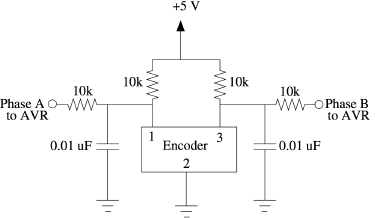
However, to actually hook up your encoder, just use the 3-pin side. Hook the middle to ground, and the "A" and "B" pins to digital pins 6 and 7 of your Arduino.
What is going on in this circuit? The Phase A and Phase B pins actually behave like switches, so the pins have pull-ups so that they will be high by default, until they are pulled low by the encoder (your Arduino actually uses its own internal pull-ups). The resistor and capacitor combo also forms a low-pass circuit to eliminate stray voltage spikes that might occur from the quick switching (this is called "debouncing"). You can use any capacitor that is up to an order of magnitude away from the 10nF value.
Use this rotary encoder code to see if you have hooked the encoder up correctly! You should see data coming in on the serial monitor -- which you can open by clicking on the magnifying glass icon in the upper-right corner of the Arduino window (or by going to Tools > Serial Monitor in the menu).
Part D. Make your Arduino sing!
Let's make the Arduino make some noise! We are going to start with the Tone example program:
Examples->Digital->toneMelody
The official Arduino tutorial for this code is also online here.
Add a 75 Ohm resistor to limit the current to the speaker when you hook it up on your breadboard. If you would like it a little louder, you can use a lower value resistor, up to a minimum of 5 Ohms.
Wire it to your circuit with the - to ground and the + to Arduino Micro pin 8.
a. How would you change the code to make the song play twice as fast?
Now change the speed back, and replace the melody[] and noteDurations[] arrays with the following:
int melody[] = {
  NOTE_D3,NOTE_D3,NOTE_D3,NOTE_G3,NOTE_D4,NOTE_C4,NOTE_B3,NOTE_A3,NOTE_G4,NOTE_D4, \
  NOTE_C4,NOTE_B3,NOTE_A3,NOTE_G4,NOTE_D4,NOTE_C4,NOTE_B3,NOTE_C4,NOTE_A3,0};

int noteDurations[] = {
  10,10,10,2,2,10,10,10,2,4, \
  10,10,10,2,4,10,10,10,2,4};
You'll also have to increase the for() loop index max from 8 to 20:
for (int thisNote = 0; thisNote < 20; thisNote++) {
b. What song is playing?
Part E. Make your own timer
Make a timer that uses any of the input devices to set a time, and then automatically (or manually, if you prefer) begin counting down, displaying the time left. Make your timer show an alert once the time is up with one of the output devices we connected during this lab, or you have available. (Hint: the sample code for Examples->LiquidCrystal->HelloWorld displays the time in seconds since the Arduino was reset...)
You should be able to draw upon awesome ideas you generated for the PreLab.
Note that for some of you, the time may seem to be decremented by 10 each second (that is, from 670=>660). Why is this? Do you think it's a hardware or software issue? Think about how 100 vs. 99 is written to the screen, and ask an instructor.
a. Make a short video showing how your timer works, and what happens when time is up!
b. Post a link to the completed lab report your GitHub repo.