ESP8266 1 channel relay module - Erratums/ESP8266 GitHub Wiki

Buy online now
About Relay Module
- This is an esp8266 based relay module.
- Wide voltage input, input voltage: DC 7V - DC 25V
- Input overvoltage protection, input with TVS, voltage exceeding 33V, automatic protection
- Input overcurrent protection
- 220V 10A relay, one normally open, one normally closed
- It's using Optocoupler
- 5v working voltage
How to use pre-programmed module
- Power the device with 12v [DC] power supply
- Once it's ON, you will notice a new WiFi network
ES-1CH-Relay, connect to that network using passwordtrytest123 - Once connected, use your browser [Google Chrome] and go to 192.168.4.1 [there is a chance the IPAddress is different]
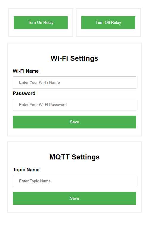
- From this page
- You can control the device with
Turn OnandTurn Offbuttons - You can configure your WiFi router Name and Password here
- You can set the Topic Name here. This should be a unique
Namewhich should be used to control device remotely from our server here - To use topic name use above link with parameter topic. Sample is here
- You can control the device with
- Please Note: It is not possible to change the Hotspot name or password without Reprogramming Device with Sample MQTT code
How to add DIY relay modules to Smart Access

How to program ?
If you don't know how to install ESP8266 into Arduino IDE, please refer this link
How to install ESP8266 in Arduino
If you don't know how to program ESP01S, please refer this link
How to program ESP01S
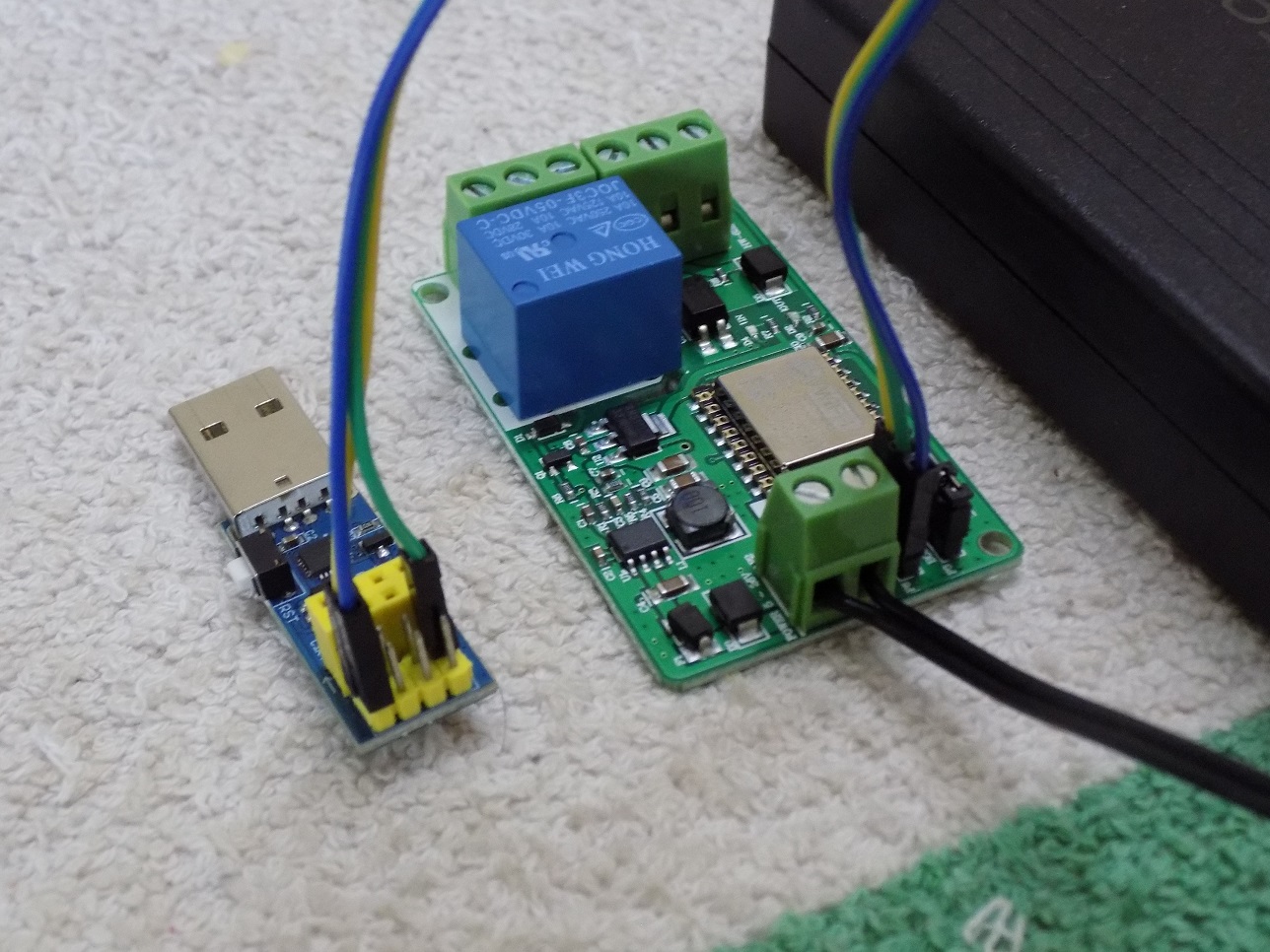
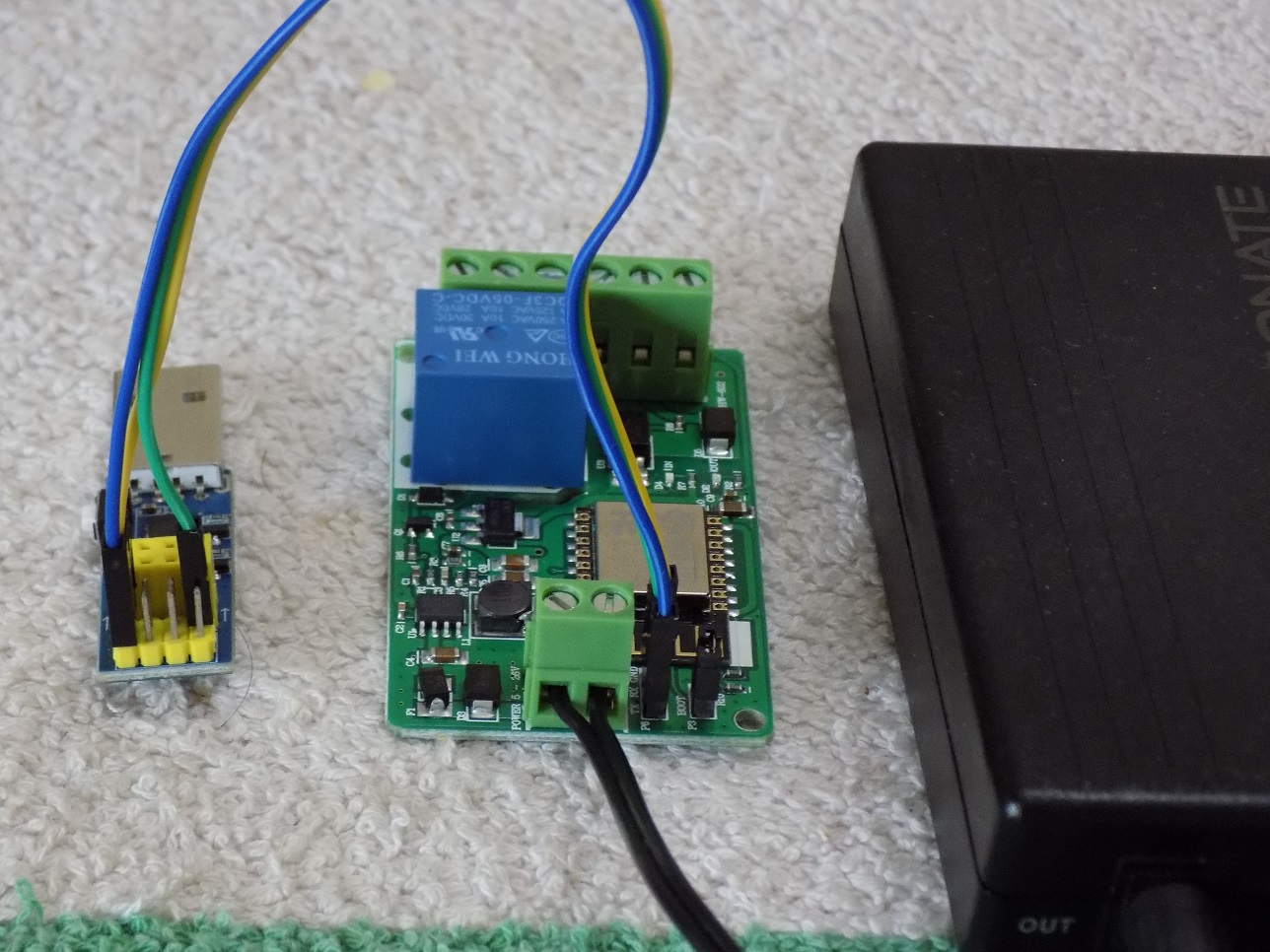
Note: Closing the Jumper will boot the Module in Programming Mode
- To program module [ESP8266], we need to close the jumper [P3]
- as shown in the below Image

+ For normal use, just open or unplug the jumper
Upload code to the module
- USB to TTL converter. You can buy it here.
- External Power Supply [Tested with 12v]
- To program the board, we need to close the jumper P3. You can see in the below image
- Connect the power supply to board
- Connect Rx/Tx to Tx/Rx of TTL converter
- Connect ground of board to ground of TTL converter
- No need to connect Vcc to TTL converter. We are already using external power supply
- Connect TTL converter to computer and upload the code
Select board type ESP8266 Generic
 |
 |
|---|
Sample Code [Basic]
You can get sample code from our Github repository
-
This is a simple code using which you can control the relay via device WiFi Hotspot
-
Once the code is uploaded, turn off the module and remove the boot jumper power on relay module
-
You will notice a new WiFi network
ES-1CH-Relay, connect to that network using passwordtrytest123 -
Then use your browser [Google Chrome] and go to
192.168.4.1[there is a chance the IPAddress is different] -
You will see the page as below. You can control the relay through this page
-


Sample Code [MQTT]
If you don't know how to install MQTT library on Arduino, please refer this link
How to Install MQTT library on Arduino
If you are interested to setup your own MQTT Broker, please refer this link
How to setup free MQTT Broker
You can get sample code from our Github repository
-
Using this code you can control relay module from any where through internet
-
This can only be used for non commercial propose. We are using free MQTT server from Beebotte
-
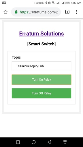
Once the code is uploaded, you can use our test client page MQTT Smart Switch to switch relay
-
If you have changed the
Topic Namein the code, then use that name here -
-
You can also control the relay and change settings by connecting to Hotspot [192.168.4.1]
-