Torso Report - DarshanNalwal/hello_world GitHub Wiki
Problem statement:
To design, build and develop an experimental humanoid robot platform that has basic artificial intelligence and achieves static and dynamic stability.
Literature survey:
To design ,build and develop a humanoid robot is a complex problem to encounter, as it has many degrees of freedom to control, use the feedback in real time and hence achieve dynamic and static stability.
We modelled our robot considering it to be a three to four years child and hence the height obtained from anthropometric data was about 94 centimetres. The weight of the robot decided to below 10 kilograms.
Then we chose the torso design where through our search found that to maintain zero moment point is a crucial factor, during dynamic walking and that during static walk was control of centre of gravity.
Then, also we considered the design of arm whose length was decided to be about 37 centimetre according to the anthropometric data as mentioned earlier. In this version of the robot we are concentrating mainly on the dynamic stability of the robot and the arm do not have much of function to do.
Revised problem statement:
To design, build and develop torso with arms that enables the dynamic stability of the whole structure, which also has the enclosure for battery placement, controller placement and touch screen for robot status display.
Requirements:
ROBOT USE CASES:
- Robot used to getup when it falls.
- Robot used to walk from one point to another point
- Robot used for evolution in design.
- Robot used for pick and place.
- Robot used in space.
- Robot used for autonomous vehicle driving.
- Robot used for welding.
- Robot used as a guide for specially abled people.
- Robot used for painting.
- Robot used to study social behaviour.
- Robot used for laboratory assistance.
REQUIREMENTS:
- Maintain CG of whole robot just above thies and ZMP inside support polygon during dynamic walking.
- Modular in design.
- Enable quasi-static evolution.
- High stifness and strength.
- Light in weight.
- Independent testable platform.
- Handel dynamic shocks.
- Wires intact at maximum stretch point.
- Robot can sustain 9g forces.
- Robot can sustain extreme weather conditions such as extreme temperature
- Robot able to collect data on atmosphere variables.
- Robot can able to run on solar power.
- Robot can understand and interpret road safety signal.
- Robot detect passer by and stop when detected.
- Robot can learn and traslate different languages.
- Robot can allow the students to learn different domains.
- Robot can conduct test to evaluate one’s performance.
- Robot can help to walk.
- Robot can wait for traffic signals.
- Robot endeffector can allow the user to insert or change brushes of different size.
- Robot can contain paint resistant coating on its exoskeleton.
- Robot controller can be based on artificial neural networks.
- Robot can able to lear different equipment hazards.
- Robot can be able to understand the behaviour of different laboratory equipment and if used for a specific laboratory it can be programmed according to that.
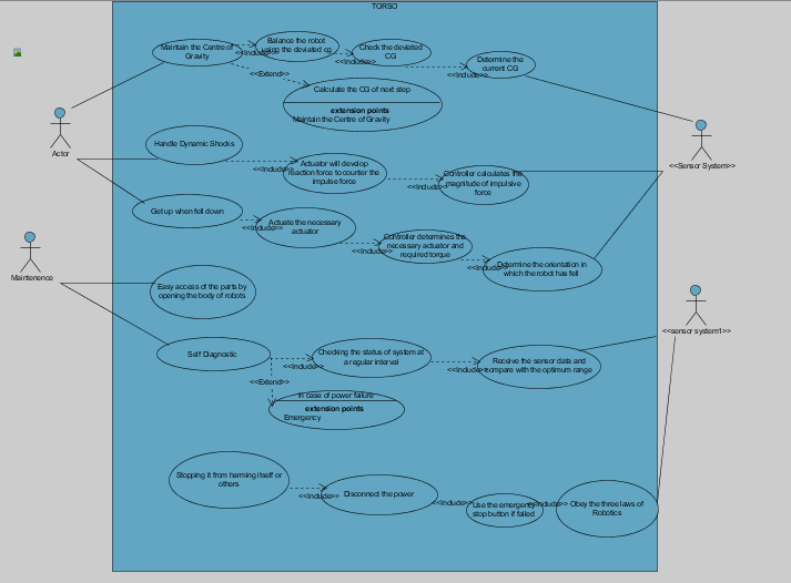
UML DIAGRAM:
Design specifications:
| SL.NO | D/W | Measure of performance | Egg units | Range value | Ideal value | Validation | Priority |
|---|---|---|---|---|---|---|---|
| 1 | D | CG position during various activities. | cm | 0-2 cm | 0 | Method Cg lies in the Convex polygon tested using simulation | 10 |
| 2 | D | No. of removable parts. | Count | 1-10 | 10 | Ease of assembly & disassembly | 8 |
| 3 | D | Features improved or added with new version. | Count | 1-20 | 20 | Reliability of new features added without conflicting the existing features. | 9 |
| 4 | D | Young’s modulus. | N/m2 | 1-100 GPa | 1.5 GPa | Stress v/s strain curve used to find young’s modulus. | 9 |
| 5 | D | Mass | Kg | 3-5 | 3 | Weighting machine | 9 |
| 6 | D | Efficiency on different platform. | % | 0-100 | 100 | Calculation of efficiency on various platform and mean deviation. | 8 |
| 7 | D | Impulsive force or torque calculation. | N or N-m | 0-6 kN | 0 | Calculation of external force & deflection of the part on which force shock is impacted. | 9 |
| 8 | D | Calculation of deflection. | cm | 0-5 cm | 0 | Checking for loose connection and removal of any wires. | 9 |
| 9 | W | Calculation of gravitational force | N | 0-2381 | 2381 | Testing on application of 9 g force. | 5 |
| 10 | W | Determination of temperature. | K | 273-500 | 298 | Temperature sensor. | 4 |
| 11 | W | Determination of humidity | % | 40-100 | 80 | Humidity sensor | 3 |
| 12 | W | Power | kW | 0.25-1 | 0.25 | Robot able to charge on solar power | 5 |
| 13 | W | Ability to detect various colours | nm | 400-500 | 450 | Calculation of wavelength light detected. | 4 |
| 14 | W | Calculation of distance between robot and next passerby | Metre | 0-∞ | 0 | Distance sensor | 5 |
| 15 | W | Ability to speak different languages | Count | 0-15 | 15 | Comparison using standard text-to-speech engine. | 4 |
| 16 | W | Ability to teach different subjects. | Counts | 0-100 | 100 | Inspection of robot database using professionals | 4 |
| 17 | W | Maximum marks allotted for test | Number of marks | 0-100 | 100 | Ability to test performance of individual. | 2 |
| 18 | W | Calculation of reaction force due to robot support | --- | 0-50 | 50 | Load sensor | 3 |
| 19 | W | Shortest path determination | m | 0-2000 | 0 | GPS sensor | 2 |
| 20 | W | No of different brushes can be attached to end effector | count | 0-10 | 10 | inspection | 3 |
| 21 | W | Ability to resist ammonia present painting | W/W | 0-1 | 1 | Calculation of weight ratio of ammonia | 2 |
| 22 | W | Ability to understand social behaviour | - | - | - | Determination of robot behaviour on various test situations | 2 |
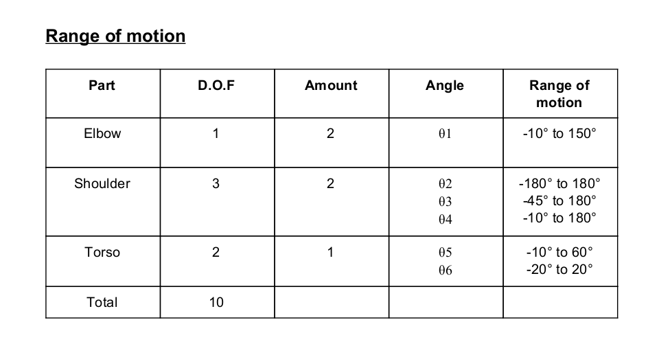
Range of motion:
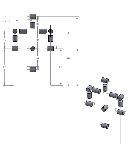
DOF of torso:
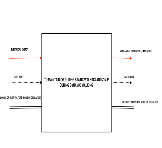
Black Box:
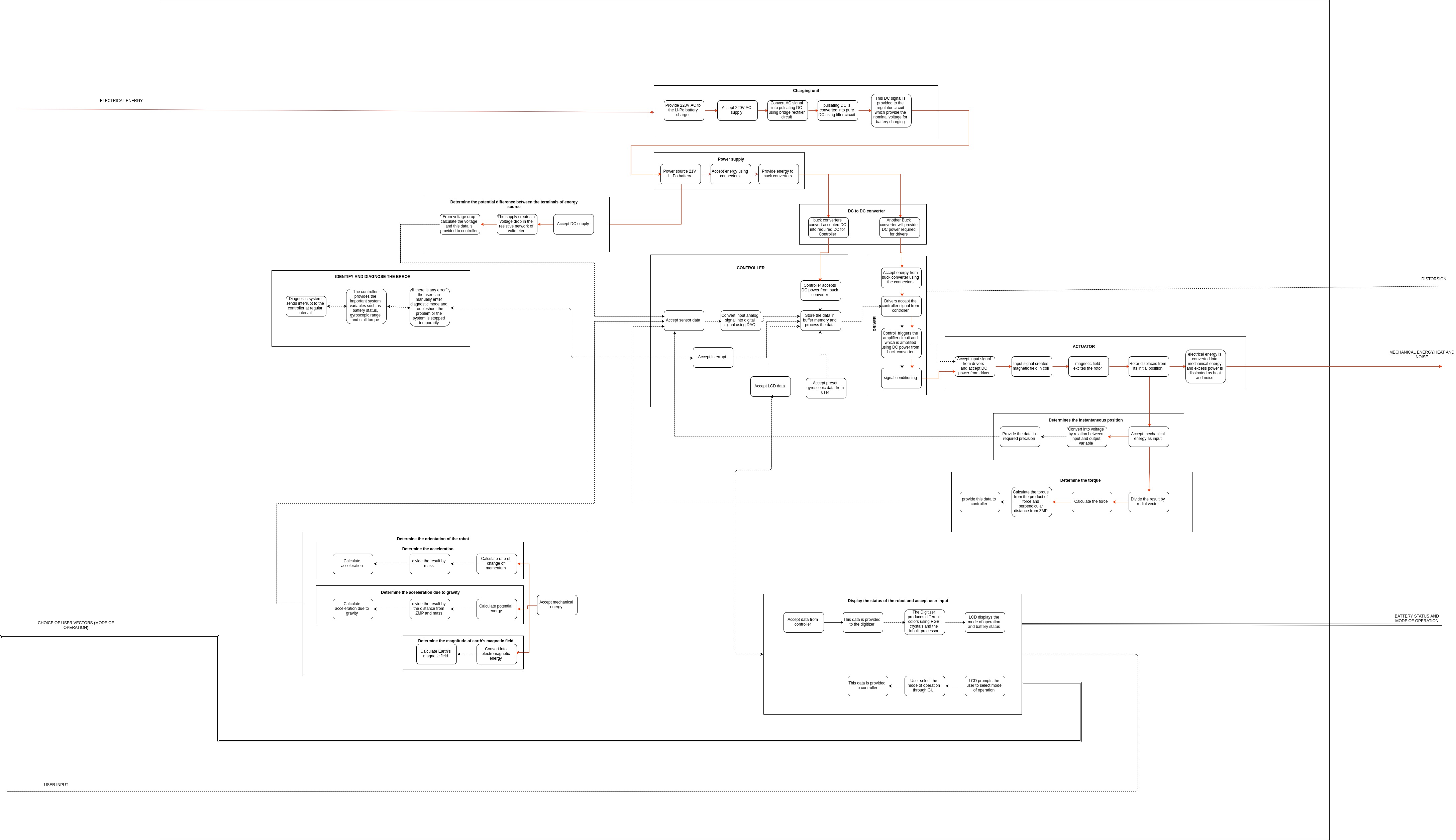
Function structure:
Morphological chart:
| Function | Solution 1 | Solution 2 | Solution 3 | Solution 4 |
|---|---|---|---|---|
| Charging unit | Li-Po battery charger | Wireless charger | ||
| Provide electrical energy | Li-Po battery | NiMH battery | Lead acid battery | Li-ion battery |
| DC to DC converter | Buck converter | voltage divider | voltage booster | |
| To process input data and provide control signal | Toradex | raspberry pi | arduino | beagle bone |
| To amplify the control signal and provide required wave form to actuate actuator | Cube servo G15 driver | ESCON maxon motor driver | ||
| Convert electrical energy into mechanical energy | stepper motor | servo motor | DC motor | Brushless motor |
| Determine the instantaneous position | Rotary encoder | Optical encoder | Linear encoder | Position encoder |
| Determine the torque | Torque sensor | Force sensor | Accelerometer | |
| Display the status of the robot and accept user input | Liquid Crystal Display | LED Display | Cathode Ray Tube Display | |
| Determine orientation of the robot | IMU | GPS | camera | |
| Identify and diagnose the error | Open loop control system | Closed loop control system | ||
| Determine the potential difference between the two terminals of energy source | Voltmeter | Multimeter |
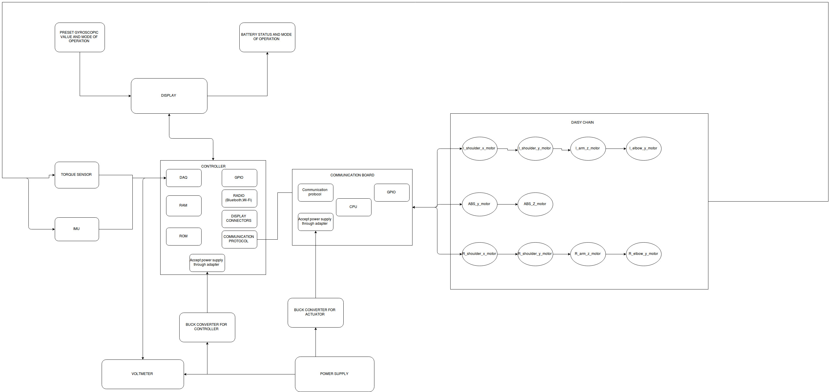
Hardware architecture:
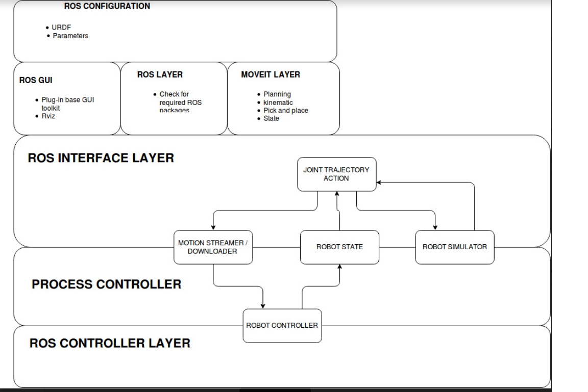
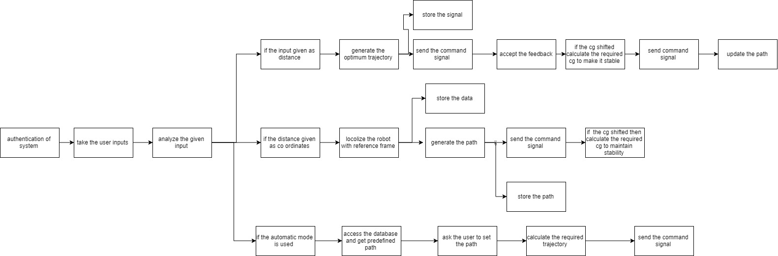
Software architecture:
Software flow:
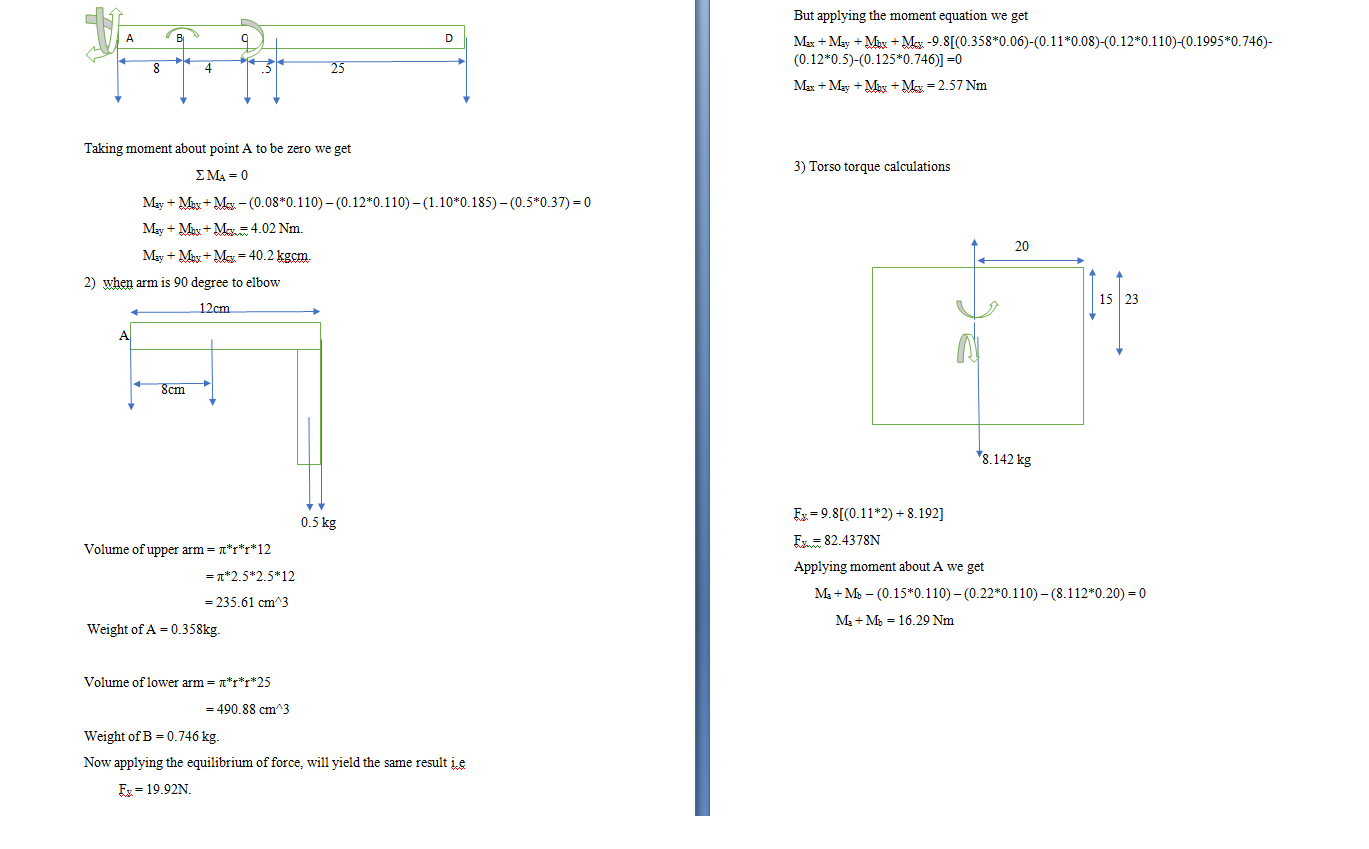
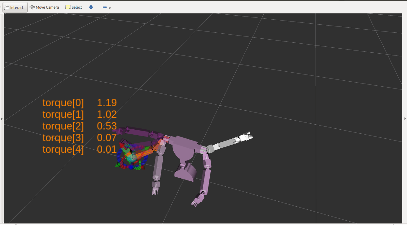
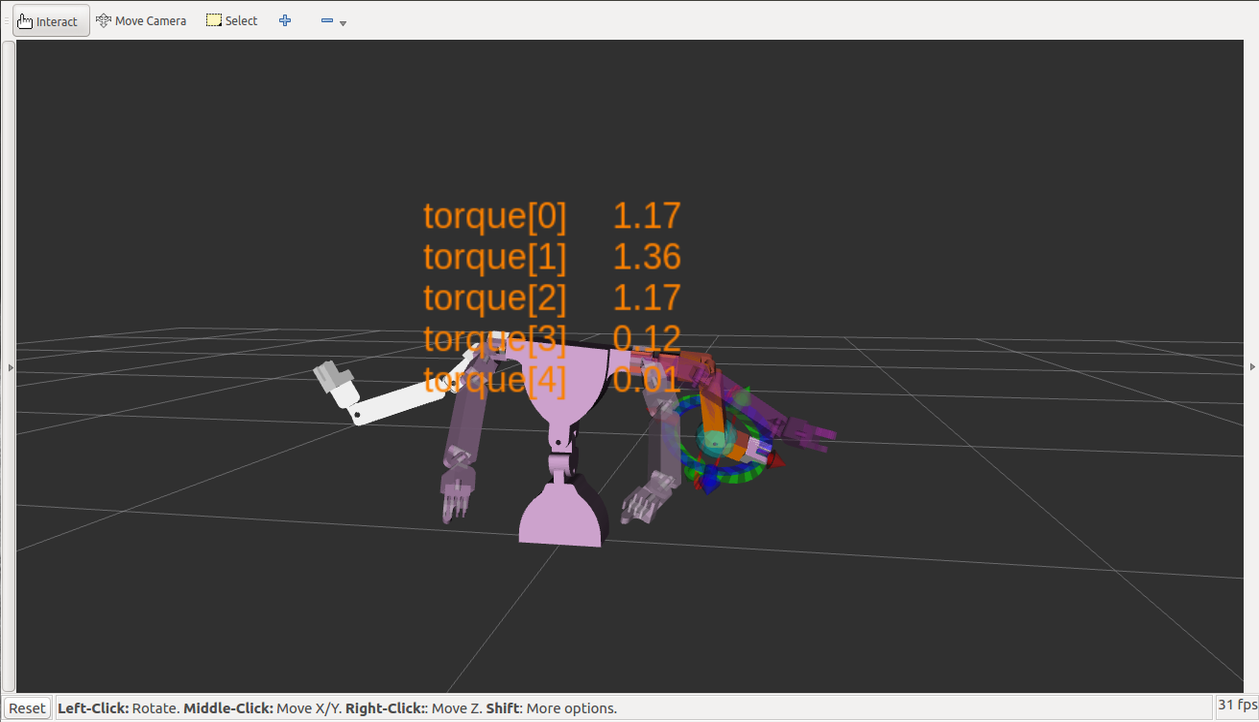
Torso and arm motor torque calculation:
Battery requirement and power calculations:
The power calculation is important step in whole of Robot design since it allows to determine the battery capacity,type of battery required and finally decide number of such batteries required.
To calculate the power required we need to first calculate the mechanical power and equate it to electrical power,where we get current and hence battery capacity.
We calculate mechanical power from the motor torque Tmot and its angular speed it to be known i.e. ωmot Now ,
         Pmechanical = Tmot * ωmot

                     = 6.4(N-m)*((54*2π) / 60)(rad/sec)

                     =33.792 Watt

         Pelectrical = IV  (if we provide a 24V supply we now require)

                   I = (33.792 / 24)

                   I = 1.408
To drive the motor for 1 hour we require
                   Q = 1.408*3600

                     = 5068 mAh
If we equire 24 such motor and hence battery capacity required would be
Q total = 121651.2 mAh
We require 12 batteries of 10000 mAh each or 5 batteries of 21600 each.
Motor selection:
REASONS FOR SELECTION:
-
Type of motor selected - Servo motor
Servo motor is selected as it suited for high precision , low motor size and closed loop control system.
-
Type of battery selected - Li-Po battery
Li-Po battery is known for its high energy density and hence its low size and it is rechargeable.
-
Type of controller selected - Toradex
-
To detect orientation of the robot- IMU IMU units are the 9 axis (gyroscope, accelerometer and magnetometer),low in cost and easy to control
Torso motor selection:
- Shoulder X and Shoulder Y = MX-64AR(4)
- Arm Z left and Arm Z right = MX-28R(2)
- Elbow left and right = MX-28R(2)
- Torso = MX-106R(2)
Torque requirements:
- Shoulder x and y is 4.02 N-m.
- Arm z 1.9 N-m.
- Elbow 1.6 N-m.
- Torso 8 N-m.
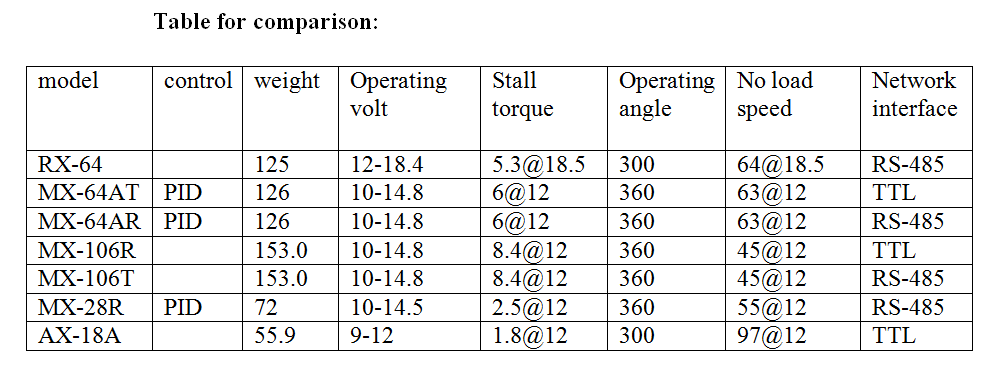
Comparison:
- Based on torque requirement calculations we end up with 3 series of dynamixel motors namely 64, 28 and 106.
- Out of RX-64, MX-64AT, MX-64AR, RX-64 not has PID control and MX 64T has TTL communication so we selected MX-64AR.
- Out of MX-106T and MX-106R , MX-106T has TTL communication so we selected MX-106R.
- Out of MX-28R and AX-18A , AX-18A not has PID control and has TTL communication so we selected MX-28R.
- TTL – has two transistors in operation which amplifies the collector leakage current hence distorted signal is included when communication is long range.
- TTL uses 3 pins for connection while RS-485 uses 4.
Motor selection table:
Torso design:
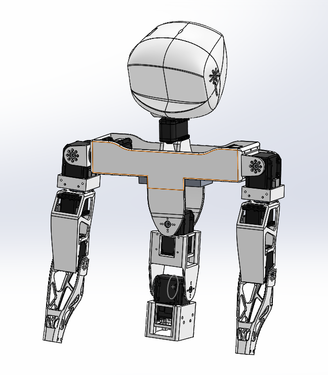
Simulation:
Comparison between Dynamixel motor and Maxon motor:
Maxon motor selection procedure:
426- ESCON 36/2 DC can take +5 V and 5 A for 10 ms.(3.3 A continuous)
i.e., if we are driving the motor at 12V it can deliver 1.5 times the stall torque for 10 ms.
To provide the stall torque in case of worst case we require to calculate the time of operation that brings it from worst case.
The maximum displacement during worst case to bring to normal state is about 90 degrees.
Now , for a 55 RPM motor (MX-64 AR) the required is
    t=(90/360)*(60/55)

     =15/55

     = 270ms
Hence, we cannot use the auxillary torque for the mtor to drive worst case.
Gear Ratio Calculation:
The required power to drive the torso motor is obtained as below
   P = (Tm*ω)
     = (8.0 Nm*2pi*55)/60
     = 40.0 W
From the above calculations we selected DCX 26 L whose torque is 46.9 Mn.
Therefore, the required gear ratio is.
  N = (8000/46.9)
    = 170.57
From the obtained gear ratio, we selected GPX26 gear.
COMPARISON BETWEEN MAXON MOTORS AND DYNAMIXEL MOTORS tabel:
| BASIS OF COMPARISON | MAXON | Maxon model | DYNAMIXEL | Dynamixel model |
|---|---|---|---|---|
| Torque (leg and torso) | 46.9mNm(without gear box) | DCX 26L (motor) | 6.4Nm (for torso ABS) | MX-64AR |
| 8-10Nm (with gear ) | GPX 26 (gear box) | 8Nm (leg and pelvis) | MX-106R | |
| Torque for arm,ankle & head | 37.2mNm(without gear box) | A-max 32 (motor) | 1Nm for head and arm | MX-28R |
| 1.3Nm (with gear box) | GP 32 BZ (gear box) | 1.2Nm for ankle | MX-28R | |
| motor-1.9Nm | ||||
| Weight | 170g | DCX 26 L (motor) | 153g | MX-106R |
| 153g | GPX 26(gear box) | 126g | MX-64AR | |
| 211g | A-max 32(motor) | 73g | MX-28R | |
| 190g | GP 32 BZ (gear box) | |||
| 40g | ESCON 36/2 DC | |||
| Cost | 1-4 (Rs-15168.00) | GPX 26 (gear box) | 1-5(Rs-28450 ) | MX-28R |
| 5-19(Rs-12380.57) | 6 unit (Rs-25776) | |||
| 1-4(Rs-13481.229) | DCX 26 L (motor) | 1-5(Rs-36501) | MX-64AR | |
| 5-19(Rs-11807.46) | 6unit(Rs-34904) | |||
| 1-4(Rs-10224.88) | A max 32 (motor) | 1-5(Rs-57040) | MX-106R | |
| 5-19(Rs-9169.83) | 6unit(Rs-54900) | |||
| 1-4(Rs-17610.24) | GP 32 BZ (gear box) | |||
| 5-19(Rs-12634.57) | ||||
| 1-4(Rs-10075.09) | ESCON 36/2 DC | |||
| 5-19(Rs-9430.34) | ||||
| Total cost( Rs) | 785367.16 | 850974.00 |
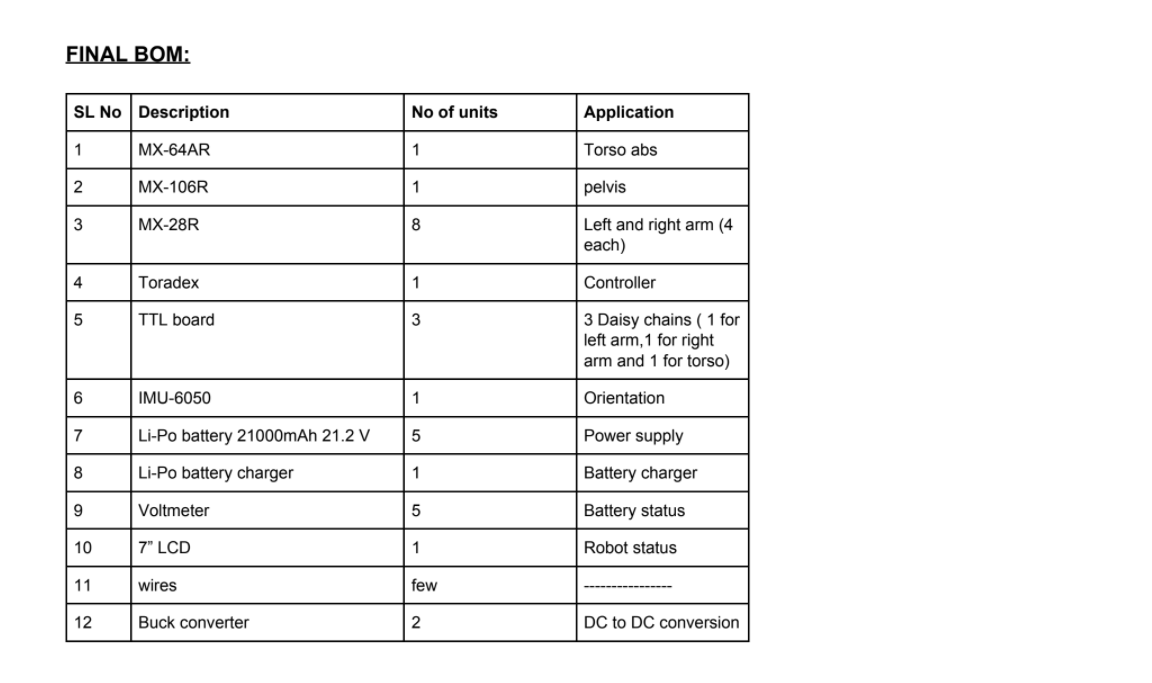
FINAL BILL OF MATERIALS:
FINAL BOM