2.Gathering Pertinent Information - D-Division-2019-2020-Odd/Repo-14 GitHub Wiki
The loss of the population of many animals results in imbalance in bio-diversity and in many schools the dissection of animals is done to teach the locomotion of animals.To replace the method of teaching about locomotion of various animals our project's main objective is to design a robot which represents the walking mechanism of various animals. This bot can be used to for other purpose like it can be used as children's toy.and moreover during the flood wheeled locomotive cannot be used and at this situation walking mechanism can be used.And upgraded model of this can be used for military to spy on enemy.
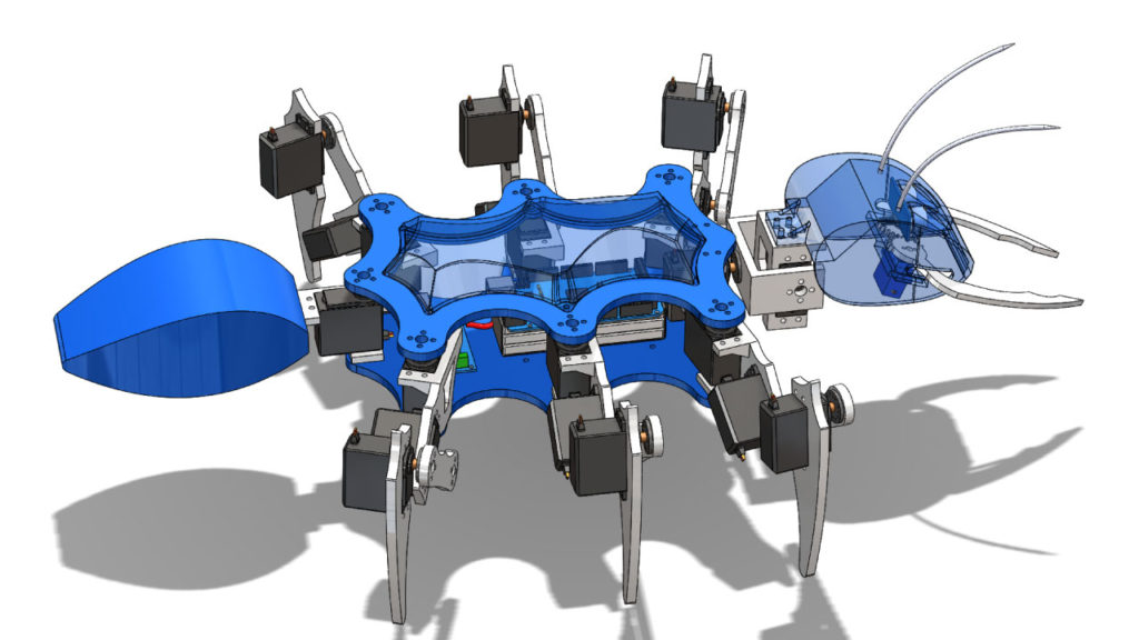
- firure.1: Ant bot
There are many attempts to achieve the objective of creating a robot to replace the crucial methods such as disection to teach the students the locomotion in animals.And there are many attempts to make a spy bot for military but there are various faults or disadvantages in there attempts.
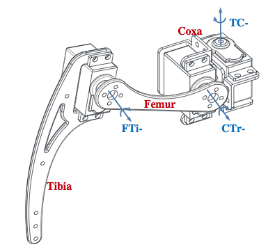
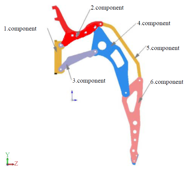
- figure 2: walking mechanism
The mechanism of this robot is inspired by the actual working of the locomotion of various insects which are having 6 legs so calling it as Hexapod is appropriate.here the robot walks by coordination of each leg where the bot lifts and swings each leg one after the other this creats the forward movement of the bot.The other mechanisms involved in the walking of bot are as follows,
- Klann's linkage mechanism
- Extra simple walker
- Chebyshev's lambda mechanism Theo jansen's mechanism
- figure :linkage mechanism
In this type of mechanism ,only one actuator is placed for one leg and it is controlled by linkage where motor is activated and a leg is lifted and placed automatically.The advantage of it is that it acquires efficiency in cost and power. Here actually each leg is attached using pin joint and motion is controlled using linkage as it is used in train wheels. Two joints are connected using one link and so on.Here locomotion for each joint cannot be controlled individually but instead the leg movement can be controlled for locomotion.[1]
The Klann linkage is a planar mechanism designed to simulate the gait of legged animal and function as a wheel replacement, a leg mechanism. The linkage consists of the frame, a crank, two grounded rockers, and two couplers all connected by pivot joints.[2]
The Chebyshev's Lambda Mechanism is a four-bar mechanism that converts rotational motion to approximate straight-line motion with approximate constant velocity.The precise design trades off straightness, lack of acceleration, and the proportion of the driving rotation that is spent in the linear portion of the full curve.[3]
There is a fixed chassis/frame where actuators are fixed at each end and using four bar mechanism the bot walks by moving
the legs to and fro this mechanism helps to give acurate velocity and movement
Jansen's linkage is a planar leg mechanism designed by the kinetic sculptor Theo Jansen to generate a smooth walking motion. Jansen has used his mechanism in a variety of kinetic sculptures which are known as Strandbeesten (Dutch for "beach beasts"). Jansen's linkage bears artistic as well as mechanical merit for its simulation of organic walking motion using a simple rotary input.These leg mechanisms have applications in mobile robotics and in gait analysis.
The central 'crank' link moves in circles as it is actuated by a rotary actuator such as an electric motor. All other links and pin joints are unactuated and move because of the motion imparted by the crank. Their positions and orientations are uniquely defined by specifying the crank angle and hence the mechanism has only one degree of freedom.The kinematics and dynamics of the Jansen mechanism have been exhaustively modeled using circle intersection method and bond graphs (Newton–Euler mechanics).These models can be used to rate the actuator torque and in design of the hardware and controller for such a system.
connectivity is an important objective to this project where in the robot can be controled by the user from distance without physical contact with the bot. Here,there are few ways of controling the bot
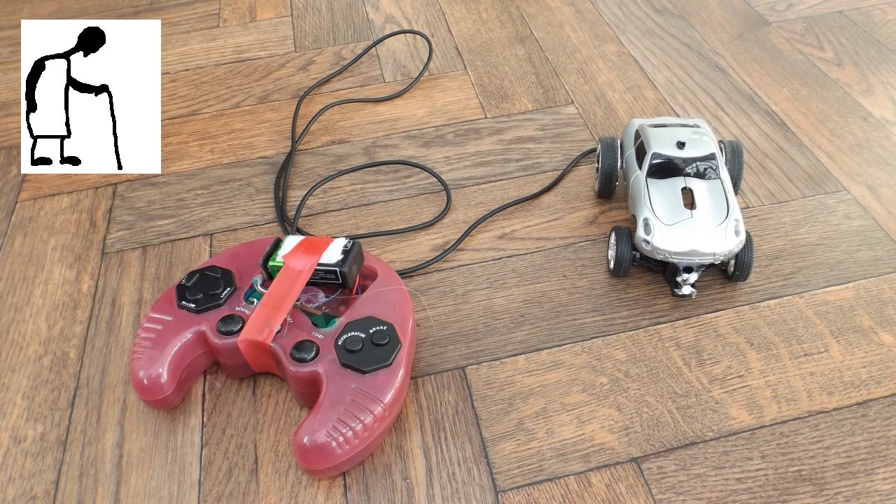
- figure 4: wired connectivity
In this method the bot is connected to a remote controler with transmition cables the advantage of this method is it reduces the complexity of the connection but makes shorter range of controling.
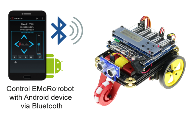
- figure 5:blurtooth connectivity
Bluetooth works by the simple principle of sending and receiving data in the form of radio waves. Every Bluetooth enabled device has a card-like attachment known as the Bluetooth adapter. It is this Bluetooth adapter that sends and receives data. A Bluetooth adapter has a particular range of connection. One electronic adaptor can notice another Bluetooth device only if the second device is present within the range of the first device. When they are within the range, they can strike up a connection between themselves. Striking up of connection between two Bluetooth devices are known as paring of devices. [2]
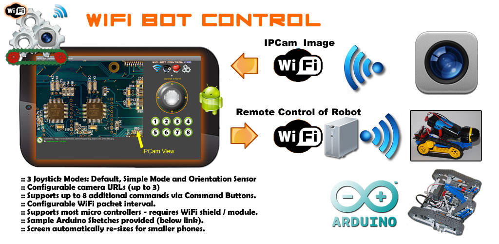
- figure 6:Wifi connectivity
For the controlling of robot a wifi module is used which can be connected to the laptop or mobile phone.After the connection an interface is designed to control the robot.using this is having high advantage because the range of this is high.
The robot can be equipped by sensors which can protect the robot from hitting the obstacle.there are ma
There are many electric components which can be used as sensors
IR sensors
ultra sonic sensors
colour sensors
temperature sensors
In this type of sensors a physical component is put like spring or any flexible instrument when it touches an obstacle it experiences stress which will stop the bot and make it turn.
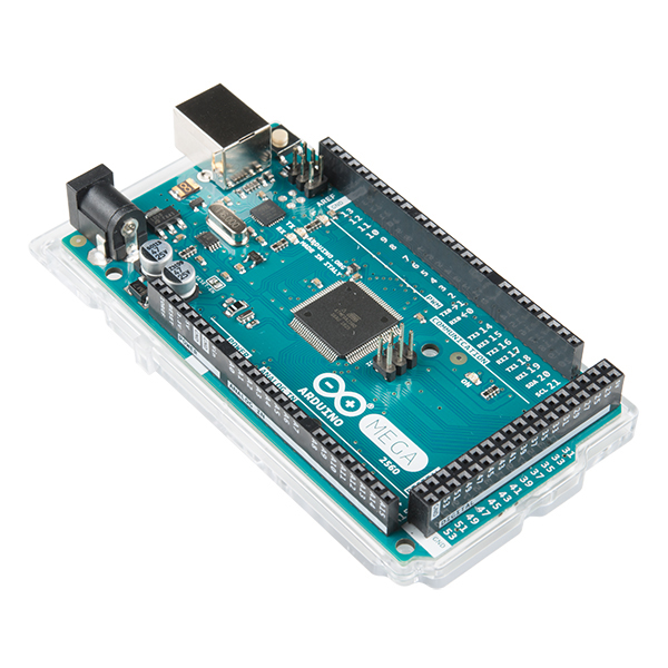
- figure 7:arduino mega
Arduino is an open source microcontroller which can be easily programmed, erased and reprogrammed at any instant of time. Introduced in 2005 the Arduino platform was designed to provide an inexpensive and easy way for hobbyists, students and professionals to create devices that interact with their environment using sensors and actuators. Based on simple microcontroller boards, it is an open source computing platform that is used for constructing and programming electronic devices. It is also capable of acting as a mini computer just like other microcontrollers by taking inputs and controlling the outputs for a variety of electronics devices.
[3]
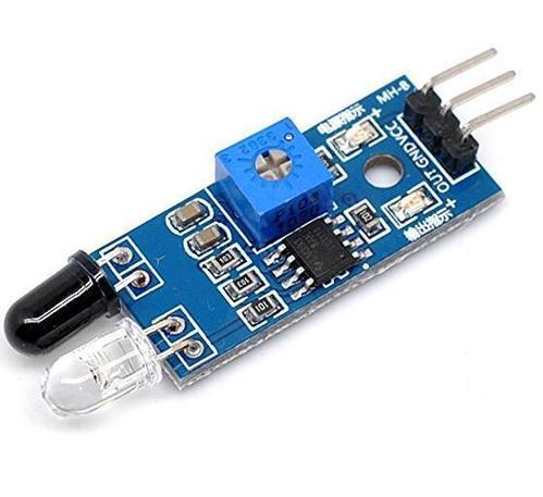
- figure 8:IR sensor
An IR sensor consists of two parts, the emitter circuit and the receiver circuit. This is collectively known as a photo-coupler or an optocoupler.
The emitter is an IR LED and the detector is an IR photodiode. The IR phototdiode is sensitive to the IR light emitted by an IR LED. The photo-diode’s resistance and output voltage change in proportion to the IR light received. This is the underlying working principle of the IR sensor.
The type of incidence can be direct incidence or indirect incidence. In direct incidence, the IR LED is placed in front of a photodiode with no obstacle in between. In indirect incidence, both the diodes are placed side by side with an opaque object in front of the sensor.[4]
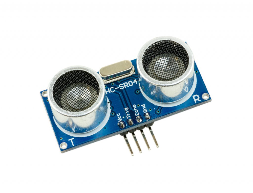
- figure 9:ultrasonic sensor
As the name indicates, ultrasonic sensors measure distance by using ultrasonic waves. The sensor head emits an ultrasonic wave and receives the wave reflected back from the target. Ultrasonic Sensors measure the distance to the target by measuring the time between the emission and reception.
Outline and detection principle
An optical sensor has a transmitter and receiver, whereas an ultrasonic sensor uses a single ultrasonic element for both emission and reception. In a reflective model ultrasonic sensor, a single oscillator emits and receives ultrasonic waves alternately. This enables miniaturization of the sensor head.[5]
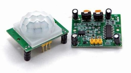
- figure 10:PIR sensor
PIR sensors are more complicated than many of the other sensors explained in these tutorials (like photocells, FSRs and tilt switches) because there are multiple variables that affect the sensors input and output. To begin explaining how a basic sensor works, we'll use this rather nice diagram
The PIR sensor itself has two slots in it, each slot is made of a special material that is sensitive to IR. The lens used here is not really doing much and so we see that the two slots can 'see' out past some distance (basically the sensitivity of the sensor). When the sensor is idle, both slots detect the same amount of IR, the ambient amount radiated from the room or walls or outdoors. When a warm body like a human or animal passes by, it first intercepts one half of the PIR sensor, which causes a positive differential change between the two halves. When the warm body leaves the sensing area, the reverse happens, whereby the sensor generates a negative differential change. These change pulses are what is detected
[6]
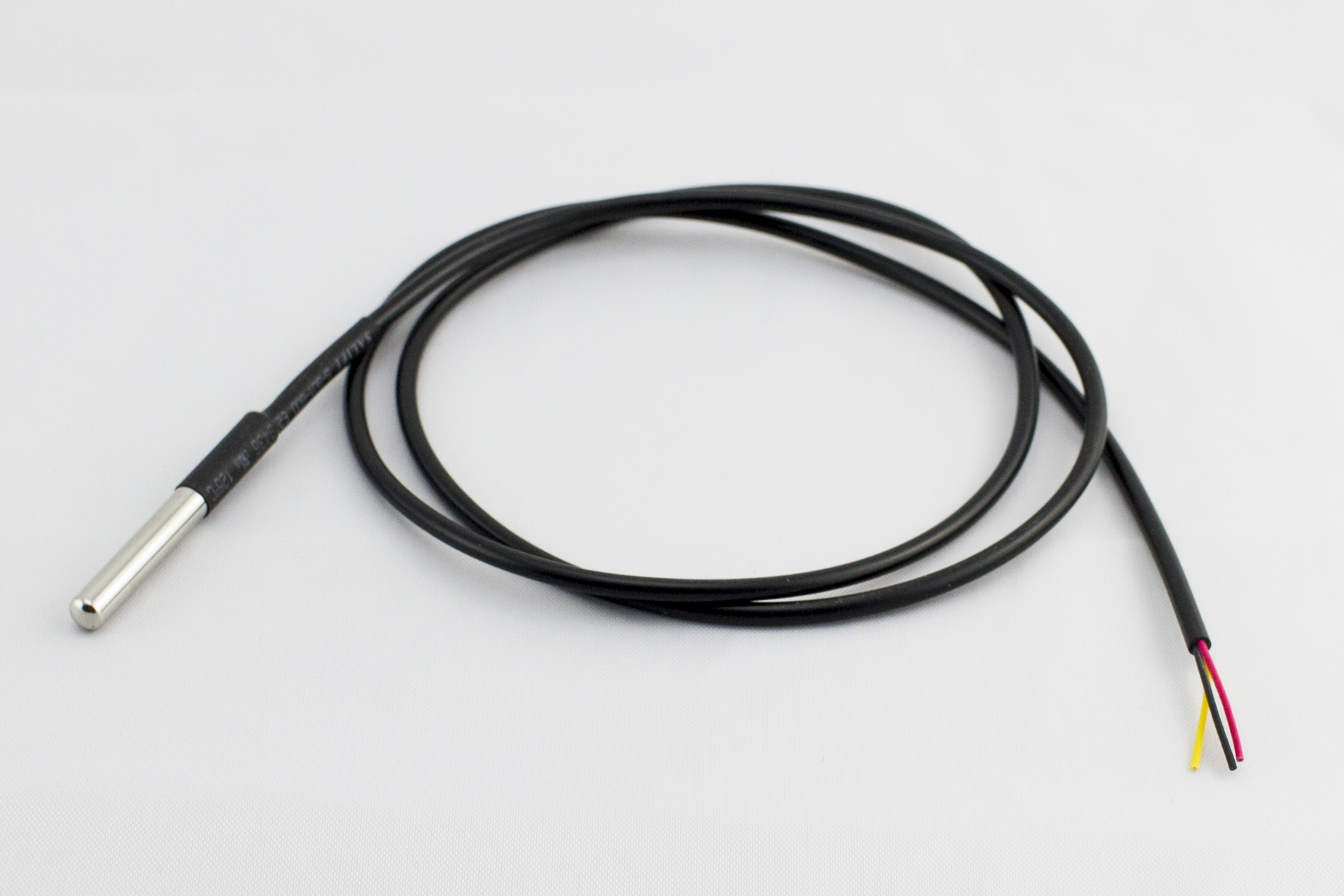
- figure 11:temperature sensor
These types of temperature sensor vary from simple ON/OFF thermostatic devices which control a domestic hot water heating system to highly sensitive semiconductor types that can control complex process control furnace plants.
We remember from our school science classes that the movement of molecules and atoms produces heat (kinetic energy) and the greater the movement, the more heat that is generated. Temperature Sensors measure the amount of heat energy or even coldness that is generated by an object or system, allowing us to “sense” or detect any physical change to that temperature producing either an analogue or digital output[7]
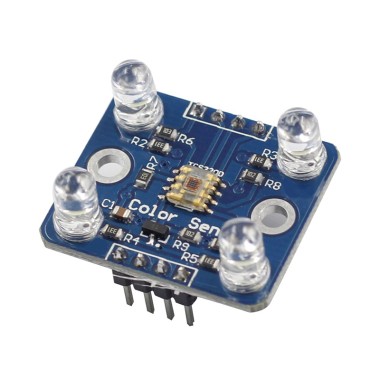
- figure 12:color sensor
The color sensor detects the color of the surface, usually in the RGB scale. Color is the result of interaction between a light source, an object and an observer. In case of reflected light, light falling on an object will be reflected or absorbed depending on surface characteristics, such as reflectance and transmittance. For example, green paper will absorb most of the reddish and bluish part of the spectrum while reflecting the greenish part of the spectrum, making it appear greenish to the observer.
Measuring colors of the ingredients are basically two ways. The easiest way is to use a color-changing light source and a sensor that measures the intensity of the light. Most industrial color sensors contain a white light emitter and three separate receivers. There are usually three sets of color source or color filter with peak sensitivities at wavelengths that we identify as red (580nm), green (540nm) and blue (450nm). All colors can be derived by their components.[8]
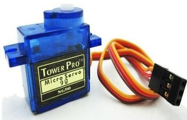
- figure 13:toy servo
Servo motors control position and speed very precisely. Now a potentiometer can sense the mechanical position of the shaft. Hence it couples with the motor shaft through gears. The current position of the shaft is converted into electrical signal by potentiometer, and is compared with the command input signal. In modern servo motors, electronic encoders or sensors sense the position of the shaft .
We give command input according to the position of shaft . If the feedback signal differs from the given input, an error signal alerts the user. We amplify this error signal and apply as the input to the motor, hence the motor rotates. And when the shaft reaches to the require position , error signal become zero , and hence the motor stays standstill holding the position.[9]
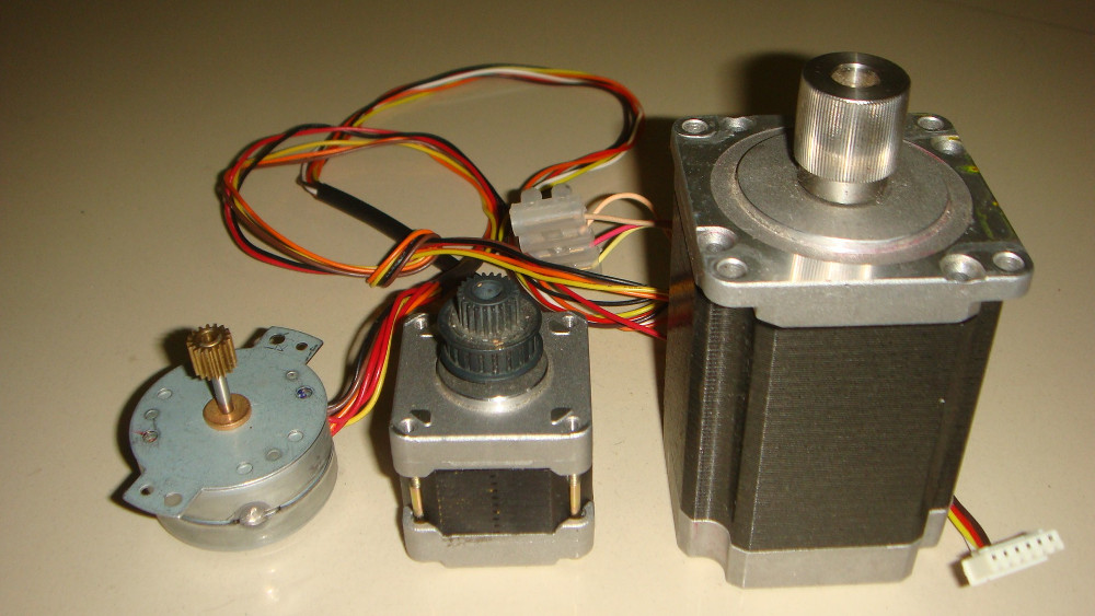
- figure 14:stepper motor
A stepper motor is an electromechanical device it converts electrical power into mechanical power. Also it is a brushless, synchronous electric motor that can divide a full rotation into an expansive number of steps. The motor’s position can be controlled accurately without any feedback mechanism, as long as the motor is carefully sized to the application. Stepper motors are similar to switched reluctance motors.
The stepper motor uses the theory of operation for magnets to make the motor shaft turn a precise distance when a pulse of electricity is provided. The stator has eight poles, and the rotor has six poles. The rotor will require 24 pulses of electricity to move the 24 steps to make one complete revolution. Another way to say this is that the rotor will move precisely 15° for each pulse of electricity that the motor receives.[10]
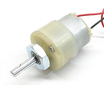
- figure 15:DC motor
A DC motor is an electrical machine which converts electrical energy into mechanical energy.
The working of DC motor is based on the principle that when a current carrying conductor is placed in a magnetic field, it experiences a mechanical force.
The direction of the mechanical force is given by Fleming’s Left-hand Rule and its magnitude is given by F = BIL Newton.
The working of the AC motor (Induction motor and Synchronous Motor) is different from the DC motor. There is no basic difference in the construction of a DC generator and a DC motor. In fact, the same DC machine can be used interchangeably as a generator or as a motor.
Like generators, there are different types of DC motors which are also classified into shunt-wound, series-wound and compound-wound dc motors. [11]
| sr no. | component name | estimated cost(in rs) | no. of item | total cost(in rs) |
|---|---|---|---|---|
| 1 | Arduino mega | 848 | 1 | 848 |
| 2 | Ultra sonic sensor | 300 | 1 | 300 |
| 3 | Toy servo | 200 | 12 | 2400 |
| 4 | Bread board | 80 | 1 | 80 |
| 5 | Single strand wires | 80 | 1 | 80 |
| 6 | Jumper wire(set of 10) | 30 | 2 | 60 |
| 7 | Lead acid battery | 500 | 1 | 500 |
| 8 | 12 volt adaptor | 150 | 1 | 150 |
| 9 | TOTAL COST | 4,418 |
Reference
- [1] https://pdfs.semanticscholar.org/742d/7ae0508933e4e79ef454359ba27e4fd56b00.pdf
- [2] https://nevonprojects.com/six-legged-spider-bot-using-klann-mechanism/
- [3] https://blogs.solidworks.com/solidworksblog/2015/09/conceptual-designer-mechanisms-chebyshevs-plantigrade-machine.html
- [3] https://www.researchgate.net/publication/326316390_WORKING_PRINCIPLE_OF_ARDUINO_AND_USING_IT_AS_A_TOOL_FOR_STUDY_AND_RESEARCH
- [4] https://electronicsforu.com/resources/learn-electronics/ir-led-infrared-sensor-basics
- [5] https://www.keyence.com/ss/products/sensor/sensorbasics/ultrasonic/info/index.jsp
- [6] https://learn.adafruit.com/pir-passive-infrared-proximity-motion-sensor/how-pirs-work
- [7] https://www.electronics-tutorials.ws/io/io_3.html
- [8] http://home.roboticlab.eu/en/examples/sensor/color
- [9] https://engineering.eckovation.com/servo-motor-types-working-principle-explained/#targetText=Principle%20of%20working%20%3A,(potentiometer)%20and%20some%20gears.
- [10] https://www.elprocus.com/stepper-motor-types-advantages-applications/
- [11] https://studyelectrical.com/2014/12/working-principle-of-dc-motor.html#targetText=DC%20Motor%20Principle&targetText=A%20machine%20that%20converts%20DC,conductor%20experiences%20a%20mechanical%20force.