5. Assembling the Keypad & Control Board - CircuitSetup/Time-Circuits-Display GitHub Wiki
The keypad, which is a replica of a TRW keypad, contains the control board, ESP32, lenses, Enter button, volume knob, SD card slot, and power supply. There are a few important assembly steps that need to be followed so the number keypad works properly with the 3D-printed keypad housing and bezel.
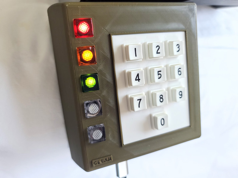
The Number Keypad
What You'll Need:
- Flush cutters or a 2.5 mm (3/32") drill bit and drill
- The current keypad printable parts listed in the printable parts README, including
keypad_bezel-v3.3mfand the correct keypad body file for your build:keypad_body_v3-4_hole_mount.3mf,keypad_body_v3_surround.3mf, orkeypad_body_v3_clear.3mf - Number keypad
- 4 small included screws
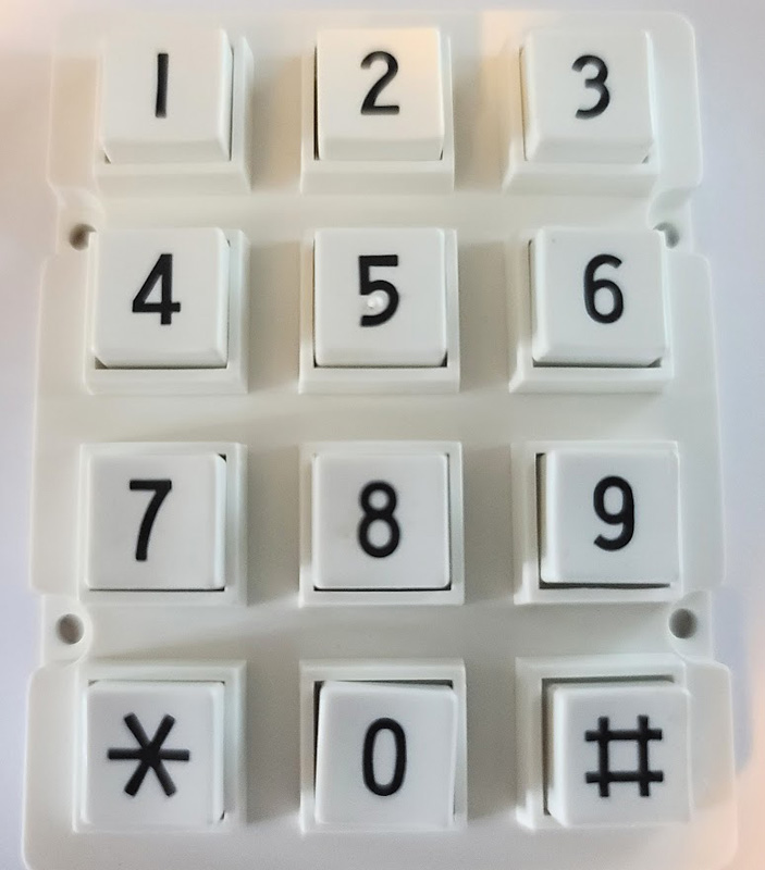
Disassembly
The number-only keypad that comes with the TCD kit needs to be disassembled. Here is how:
- Use flush cutters to cut the plastic welds off the back of the number keypad, or use the 2.5 mm drill bit to drill out the plastic welds. This method may be easier.
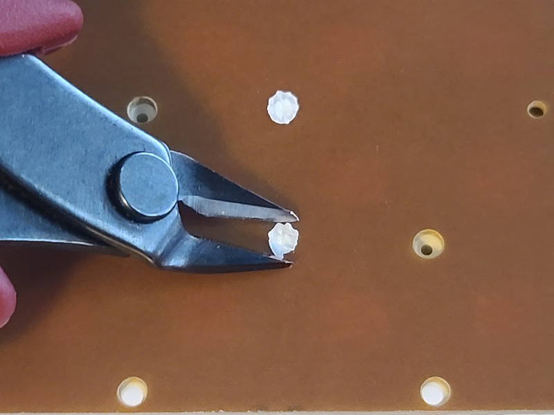
- Carefully separate the keypad PCB from the white plastic housing.
- Remove the rubber key membrane and keys.
- Put the keys into the 3D-printed keypad bezel, leaving out the
#and*keys. Make sure the keys are in the correct direction and order. If any key fits tightly in the bezel, carefully trim the opening with an X-Acto knife. - Place the rubber key membrane over the back of the keys with the black pads facing up.
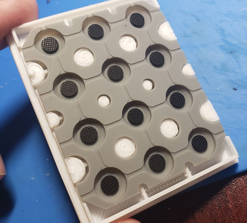
- Insert the modified keypad assembly from the front of the keypad body. This part is easier if you hold the keypad with the key faces pointing down.
- Screw together the keypad PCB and the 3D-printed bezel. Make sure the PCB sits flush with the green keypad case. The cable connector on the PCB should point toward the bottom. Tip: The screws may go in more easily if the screw holes in the bezel are drilled out with a 1.5 mm drill bit.
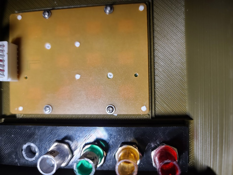
The Enter Button & Lenses (v1 & v2)
What You'll Need:
- 5 colored LED lenses
- The current lens-mount parts listed in the printable parts README, including
keypad_lens_mount_v2-1.3mfandkeypad_enter_spacer.3mf - A small saw that can cut plastic
Cut the enter button
- The Enter button needs to be cut just below the threading to fit properly in the keypad body.
- Insert the Enter button spacer into the lens after cutting is complete. This pushes the Enter button on the control board PCB.
Put in the lenses
- Remove the nuts from the LED lenses.
- Insert the lenses into the lens mount in this order: red, yellow, green, white, and white for the Enter button. Then screw on the nuts.
- Do not install a nut for the Enter button.
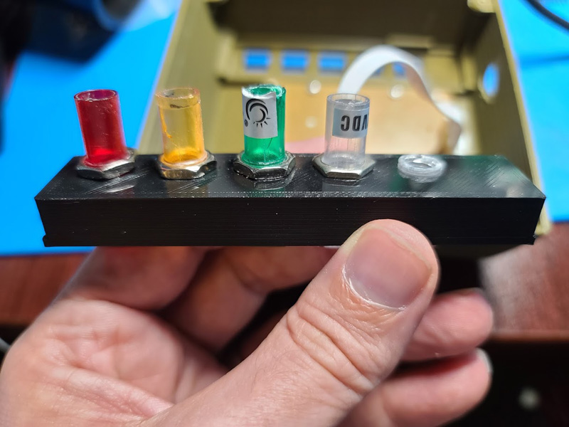
- Carefully snap the lens mount into the keypad housing. It will be a tight fit, and trimming of the bracket and/or housing may be required.
The Control Board
What You'll Need:
- Control board
- 4 included screws
- 7p ribbon cable
- Phillips screwdriver
Joining Control Board & Keypad
- Connect the 7p ribbon cable from the control board to the keypad PCB.
- Carefully align the LEDs and Enter button with the lenses already installed in the keypad.
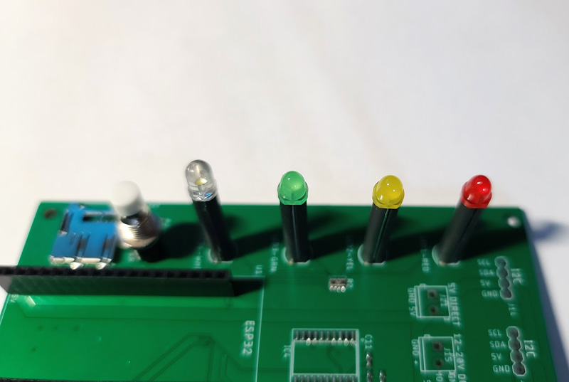
- Make sure the control board sits flush with the mounting tabs of the keypad housing.
- Use your Phillips screwdriver to secure the control board to the keypad with the 4 provided screws.