3. Assembling & Wiring the Display PCBs and Speaker in Their Enclosures - CircuitSetup/Time-Circuits-Display GitHub Wiki
Assembling the Display PCBs (3d printed)
- Enclosures come partially assembled to prevent damage during shipping. Note the position of each display enclosure in the outer enclosure:
- Top - Destination Time - Red
- Middle - Present Time - Green
- Bottom - Last Time Departed - Yellow
- Remove the display enclosures from the outer enclosure using a screwdriver
- Insert the display PCBs into the display enclosures
- The front of the displays should sit flush with front of the enclosures - you may have to trim the plastic for a good fit
- Each PCB is secured to its enclosure with 6 screws - It is okay if they screws are tight to the PCBs, but do not over tighten them

Wiring
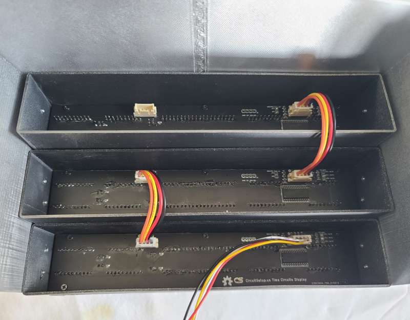
- Attach the included wires like the above picture - the Destination time only uses one wire connector
Speaker
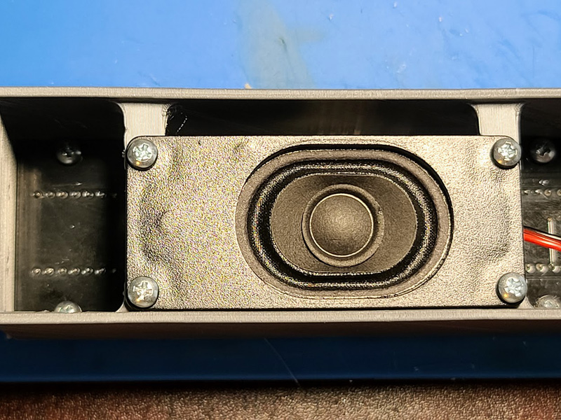
- The speaker is housed in the Last Time Departed enclosure
- Secure it with 4 screws
- Route the wire down through the hole on the right and plug it into the control board

Assembling the Display PCBs (metal enclosures)
-
Enclosures come partially assembled to prevent damage during shipping. Note the position of each display enclosure in the outer enclosure:
- Top - Destination Time - Red
- Middle - Present Time - Green
- Bottom - Last Time Departed - Yellow
-
Remove the 3 screws in the back of the display enclosures to remove their covers.
-
Take care not to mix up the display enclosure covers.
-
Note the order of each display enclosure and which display PCB should be inside of it:
- The Destination Time enclosure does not have a wire hole on the top.
- The Last Time Departed enclosure has 3 holes on the bottom to attach the keypad.
-
Put the enclosures on a table in the correct order
-
With the stand-off hardware, start by securing the stand-offs to the PCBs with the threaded ends going through the 3 top holes. Secure them with the supplied nuts.
-
Next, assemble the display PCBs in the enclosures like in the following picture:

-
Be sure to route the wires through each hole, and plug them into the display PCB before putting the cover on each enclosure. It helps to lay out the enclosures in the correct order to run the wires between the displays, like in the following picture:
-
Put on the top cover of the enclosure - the front has a notch for each screw that holds the PCB. Make sure it is all the way down so the sides and top are flush.
-
Tighten the 3 machine screws in the front, then the 3 screws in the back (they are not interchangeable)
-
At this point all display enclosures should be assembled and the 3 wires should be hooked up between each of the 3 enclosures.
-
Finally, starting with the top Destination Time enclosure, secure each enclosure to the outer enclosure by using 4 supplied screws.