4. Programming a Mecanum Drivetrain(Robot‐Centric and Field‐Centric) - CenterStage-23-24/CenterStage GitHub Wiki
The mecanum drive is one of the most common drivetrains used in FTC. The main reason for this is that the mecanum drive opens up a wide variety of movement allowing for speed and efficiency. Mecanum wheels allow the robot to move forward, backward, left, and right, but also adds a movement called strafe, where the robot can 'slide' to the side. This movement to the side is called strafing. Here is an example of the strafing movement.
Before we get further into the tutorial it is important to know the programming language Java. Here is a short course on the language. If you decide not to use Java, FTC also allows block coding. This tutorial will use Java, but if you choose to use blocks I still recommend reading the tutorial to learn the concepts of programming a mecanum drivetrain. Also, in this tutorial, we will use the Android Studio software to code. This article will walk you through installation and how to use Android Studio. I highly recommend using Android Studios, but if you are unable to you can use a web-based version of it called OnBotJava.
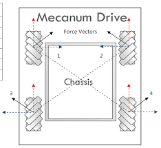
The mecanum drive allows the robot to move in any direction due to the engineering of the mecanum wheels. The mecanum wheels have their rollers at a 45-degree angle from the wheel. Because of this, when the mecanum wheels drive on the ground, the force created is 45 degrees from the wheel. With this feature, the robot can be moved in almost any direction. Great video on the engineering of mecanum wheels and how their special movement is achieved. However, in order to get the best results, the wheels must also be positioned properly. The wheels should be placed on the robot such that the rollers of the wheels form an X when looking at the robot from above. The image below shows the “X” formed by the wheels. The image also shows that the force produced by the mecanum wheel is diagonal because its rollers are angled at 45 degrees. Splitting up the diagonal force we can see the Y component (vertical orange arrows) and the X component (horizontal blue arrow). We will be exploring these components in detail later on.
The two ways of programming a drivetrain are robot-centric and field-centric. In a robot-centric drivetrain, the robot moves relative to itself. For example, if the driver were to push forward on the controller the robot would go in the direction where its front face is pointing. On the other hand, a field-centric drivetrain will move the robot relative to the field. In this case, if the driver were to push forward on the controller the robot would go in the direction of the field’s front face. The robot-centric drivetrain is easier to code and great for beginners. However, the driver must know at all times where the front face of the robot is. Both the robot-centric and the field-centric drive train have their advantages and the choice between the two is highly based on driver preference.
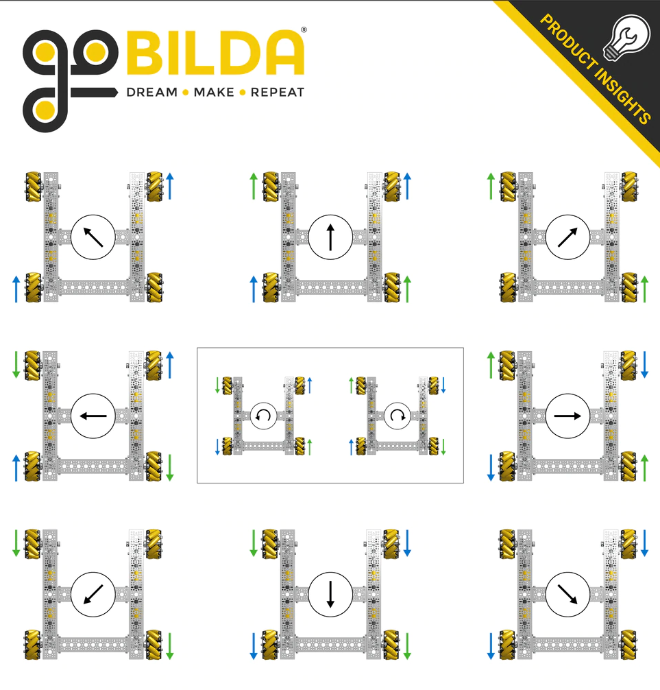
To move the robot in the desired direction we must move each mecanum wheel in a certain direction. It is important to understand the logic of where forces must be applied before programming the drivetrain(The video linked in the engineering of the wheels section is very helpful). There are four main types of movement as demonstrated in the below image(I will be referring to this GoBilda diagram throughout the tutorial): forwards/backwards, strafing in a straight line, strafing at an angle, and rotating(left and right turning).
Vertical Movement
When we move all the wheels forward the forces shown in the below image act on the robot ultimately moving the whole robot forwards. The forces created are diagonal to the wheels as the rollers are at a 45-degree angle to the wheel. Each force has an X component and a Y component (depicted by the dashed lines). When we put an equal force on each wheel, in the positive direction, we can see that the X components are canceled, allowing the Y components to move the robot forward.

Strafe To attain the motion of strafing we must move two diagonal wheels in one direction and the other two in the opposite direction. The forces for strafing are the same as vertical motion except the final force created is in the direction of the X component arrows. In this case, the Y components are canceled allowing the X component of the forces to move the robot horizontally. The below image depicts this:

To strafe the robot diagonally, we must simply eliminate one of the two forces created from the horizontal strafe so that the Y component is not canceled. To do this we move 2 of the diagonal wheels but keep the other two stationary. When this happens both the X and Y component of the forces act on the robot, moving the robot in a diagonal fashion. The image below illustrates this:

Rotation The last type of motion is rotation. To attain this motion we must move the left wheels in one direction and the right wheels in the opposite direction. All forces created are canceled out with each other, not allowing the robot to move out of its position. However, the forces do create torque(A force that causes an object to rotate about its center) allowing the robot to rotate.

Now we will start programming the robot in a Robot-Centric way. First, we need to declare a DcMotor for every wheel. Then we need to name the motors for the hardware map. This is the name that will show up in the driver station configurations. After doing this we must also reverse the front right and back right motors. We do this because the left and right motors are placed as a mirror image of each other and would move in opposite directions due to this. So, we must reverse either the left or the right motors. With most motors, you would choose to reverse the right motors because when powered with a positive value the motors would move in a clockwise direction. The code is shown below:

Now, we must set power to each wheel in a way that the wheels of the robot move in the way shown in the GoBilda diagram. In order for the wheels to be powered correctly we must find the equations of power for each wheel.
The first thing we should do is create a double variable for vertical movement(forward, backward), horizontal movement(strafe), and rotation(turning). We will use these variables to set the power of each wheel. We will set the value of all these variables to a certain button on the controller of the robot. However, the value of the vertical variable will be negative to make the motors rotate in a clockwise direction. The variables with their values are shown below.

Now we will use the method setPower() on each wheel to set the power of each wheel with the variables we made above. The first thing we know is that to go forward or backward we must move every single wheel forward or backward. So, what we can start with is setting the power of each wheel to the vertical movement variable. When we go completely forward with the controller, all the wheels will be set to a power of 1 and when we go backward the wheels will be set to a power of -1. The code is shown below.

Now we will add the horizontal variable to the power of the wheel in order to strafe. As you can see in the Go Bilda diagram, two diagonal wheels move in one direction while the other two move in the opposite direction. So, we must add the strafe variable to two of the diagonals and subtract the strafe variable from the other two diagonal wheels. If we go right on the controller the vertical value is set to 0, setting the power of the wheels to the X value. However, if we want to create a diagonal strafe we must push the joystick in a diagonal direction. Let us take the example of moving to the front and right. Two of the diagonal wheels will be set to the power of 1 + 1 = 2 (1 is from the vertical variable and the other 1 is from the strafe variable). The 2 will be changed to a 1 by the Software Development Kit(SDK) as the power cannot be set to a value greater than 1. On the other hand, the other diagonal wheels will be set to a power of 1 - 1 = 0. Two diagonal wheels will move forward since they have a power of 1 and the other two will not move since they have a power of 0 allowing an angled strafe. The code is shown below.

The last thing we will add to the set power method is the rotation variable. As you can see in the Go Bilda diagram, you must move the right wheels in one direction and the left wheels in the opposite direction. So, you must add or subtract the rotation variable from the right wheels and do the opposite with the left wheels. After that, the math behind strafing and rotation is the same. To create a rightward curve the same principle applies as when creating a rightward diagonal strafe.

Now that we have the main parts of our drive train coded we can add some things to improve our program. The first thing we can do is multiply the strafe variable by a number slightly higher than 1 in order to stop flawed strafing. We will multiply the variable by 1.1 but you can change the value as needed. We need to do this because the mecanum drive is less efficient at transferring power into speed while strafing because some of the energy goes into spinning the rollers (This also means that strafing is slower than other movements on a mecanum drive). When we multiply the power by a number slightly greater than 1, it ensures that the strafe speed will be the same as the other speeds. This is important as it improves accuracy for angled driving.

The second thing that we can do to improve our program is to make sure that the power of the wheels does not go above 1. If the power does go above 1, the SDK will truncate the power and read the power as 1. The program will not have an error, but this will not apply the correct power to each wheel of the robot. Due to this incorrect ratio between the powers, the movement will not be consistent. What we can do to solve this problem is divide the power of every wheel by a certain number so that every power is less than 1 and the ratio of the power of each wheel stays the same. To find what number we must divide the power of each wheel by, we must figure out if the absolute value(Math.abs method) of each of the power variables(vertical movement, strafe, turning) added together is greater than or less than 1(use the Math.max method for this). If it is greater than 1, we use that value to divide and if not, we divide the power of each wheel by 1 (We use the variable maintainRatio to divide. It will hold either the value of the variables added up or 1). We use the absolute value of each variable because if they are negative, we do not want to divide by a negative number and have an issue in direction while driving.

One thing we can do to make driving easier is add brakes. To do this we will essentially say that we the power on the gamepad is equal to zero set the power of the motor to zero. This will eliminate the robot from drifting as the motor’s power will instantly be set to zero when the power in the gamepad is set to 0. The code for this is shown below.

To see the powers in real-time, we can print out the power of each wheel on the driver station. To do this we must use telemetry. There are two simple methods we must use. One is telemetry.addData, through which we can add values to print. The first parameter in this method is a caption and the other parameter is where we place the value. Once we have added all the values we wish to print, we can call the telemetry.update() method which prints all the information onto the driver station.

Now to run the code we must organize it in a special way. One thing that is necessary for the code to run is to import libraries. We will import DcMotor, DcMotorSimple, Gamepad, and HarwareMap. You can write out the import, but an easier way is to type the class name (DcMotor, Gamepad, etc), which will automatically import the library.
Now inside the class, we will create the motors. After that, we will create the gamepad and telemetry so that we can take gamepad values and print them out with telemetry. We will create a special type of method called a constructor, this is a special type of method that will run automatically when an object of the class is made. To learn more about constructors and object-oriented programming please click here. The name of the constructor is the same as the name of the class and a constructor does not have a return type. Inside the constructor, we will include our hardware mapping (for the driver station), reverse the right motors, and add brakes. We will also initialize the gamepad and telemetry. Inside the loop() method, we will include the code to set the power of each wheel.

Now to run the drivetrain we will create a separate class. We will include @Teleop to display this code in the Teleop section on the driver station. Now we will create a class called drivetrain for our code and this class will extend LinearOpMode. OpMode and LinearOpMode are two basic classes that FTC provides (Learn more here). In this tutorial, we will be using the class LinearOpMode. When we use the keyword extends, we are basically saying that all the things in the LinearOpMode class will come into our class(Learn more here). We must also create an object of the DriveTrain class(check out this link for more information on object-oriented programming). We will then create the main method in the LinearOpMode class, runOpMode, that runs automatically when the class is initialized in the driver station. Inside this method, we will initialize the object(the constructor in the RobotCentricDriveTrain class will run here). After that once the start button is pressed on the driver station we will run a loop in which we call the loop method from the other class. This loop will keep running until the stop button is pressed.

This was an in-depth explanation on programming a robot-centric mecanum drivetrain. If you would like a simpler tutorial please check out this link. If you were unable to understand any of the concepts in this tutorial, I have listed all the resources I used to create this document below. You can check them out and explore more on your own. I recommend contacting veteran FTC team members if you still have difficulty understanding (I needed to get some help from other teams to understand some of the logic).
- Mecanum Drive - Game Manual 0
- The Brilliant Engineering of Mecanum Wheels! - YouTube
- How to Use Mecanum Wheels in 200 Seconds - YouTube
- How To Program a Mecanum Drive Train (teleOp) - YouTube
- Mecanum Wheels Tips & Tricks - YouTube
- FTC Mecanum Drive Train: Pros, Cons, Programming Tutorial - YouTube
- Mecanum Wheels Tutorial - YouTube
- FTC 2 Minute Tutorial: Mecanum Drivetrain - YouTube
- Mecanum wheel - Wikipedia
- Drivebases - FTCLib Docs
- Using Telemetry - Game Manual 0
- Android-studio-guide.pdf
- Java With Mosh
Now we will start programming a field-centric mecanum drivetrain. The field-centric drivetrain code has many similarities with the robot-centric drive train as we will still need to create 4 motors, name them for the hardware map, reverse the right motors, create 3 variables(verticalMovement, strafe, turning) to set the power of the robot, set the power of the robot with the same equation, and maintain the ratio of the powers in case they go above 1. The main different thing we must do in a field-centric drive is rotate the translation joystick (strafe and verticalMovement) opposite to the angle of the robot. So, if the robot has been rotated -90 degrees (which is 90 degrees clockwise) we must rotate the joystick 90 degrees (which is 90 degrees counterclockwise). However, it is important to note that we are not rotating the joystick but the inputs of it. These inputs are vectors.
To get the robot's angle we must use a tool called IMU (Inertial Measurement unit). IMU is a device that provides the orientation of an object. An IMU is included inside all control hubs in FTC. To get the robot’s orientation the robot coordinate system is used. The robot coordinate system has 3 axes: The X-axis which points out the right side of the robot, the Y-axis which points out the front of the robot, and the Z-axis which points up to the sky. The Heading or Yaw is the measure of the rotation about the Z-axis, the Pitch is the rotation about the X-axis, and the Roll is the rotation about the Y-axis. For the field-centric drive, we will be using the heading/yaw.
Now we will configure the IMU. There are two different classes for imu and both of them are configured in a different way. In this tutorial we will be using the BN0055IMU class. However, you can find instructions on configuring the IMU class on this document. Like all configurations, we will use hardwareMap.get(). However, the imu needs to be initialized in a special way. We will also set the measure of the heading to Radians as this will help us in our future calculations.

Now we will create a variable to store the heading of the robot. To do this we will get the first angle using the IMU. The first angle is the angle of rotation about the Z-axis which is the heading.

We will then choose a button to reset the heading of the robot. The IMU automatically resets when the OpMode changes (Autonomous to Teleop). However, it is useful to have a button to reset the heading in case there is a disconnect or any other failure. To reset the heading we simply have to make a conditional statement saying that if a button is pressed, reset the heading. In this tutorial, we will be using the right bumper to reset the heading.

Now we will rotate the joystick counter to the robot’s heading. To do this we must treat the joystick inputs as vectors and then rotate them according to the position of the robot. To review from before, the vectors for translating in a robot-centric drive train are shown below.

Take a close look at the forward vectors. Now let us assume that we want to go forward in our field-centric drive train but the robot is rotated -90 degrees (90 degrees in a clockwise direction). So, to go forward the forces that act on the robot are the same as strafing to the left. So, we must add code so that when we go forward on the joystick the robot strafes to the left. To do this we must rotate the vectors using the 2D vector rotation formula given below. To view a proof of the formula click here.
                                            x2=x1cos()-y1sin()
                                            y2=x1cos()+y1sin()
Before we get too much into the formula, notice the similarity between the left strafe and forward vector diagrams. To understand this similarity better let us try to make the left strafe diagram using the forward diagram. The first image shown below is the normal forward diagram. In the second image, we rotate the whole robot -90 degrees (90 degrees clockwise) meaning that the heading of the robot is -90 degrees. After that, we rotate the position of the vectors counter to the heading of the robot at a 90-degree angle(This is what we mean by rotating the joystick counter to the heading of the robot).

Now that we know what vectors we must rotate and we must rotate them with the vector rotation formula let us take a look at why the formula works. Let us start with a vector on a coordinate plane. The vector is named A and has coordinates <x,y>.

Now we will create a right triangle out of this vector. The vector will become the hypotenuse of the triangle and the x and y coordinates will become the lengths of legs of the triangle. We will use the angle a to calculate the lengths of x and y. In trigonometry, the sine function is equal to the opposite side of the angle(y)/hypotenuse(the vector). So, sin(a) = y/h and y = h(sin(a)). To find the value of x we will use cosine which is equal to the adjacent side of the angle(x)/hypotenuse(the vector). So, cos(a) = x/h and x=h(cos(a)). For a full tutorial on right triangle trigonometry please click here.

Now we will rotate vector A by angle b, becoming A2. It is important to note that the length of the vector h will stay the same despite this rotation. Now we will once again make a right triangle out of this vector. The length of the vector(or h) will be the hypotenuse while x2 and y2 are the length of the legs of the triangle. To find the length of y2 and x2 we will again need an angle. We will be using the angle formed by the hypotenuse and leg x2 and its value is a+b. Using the sine and cosine functions we can find that the length of y2 is h(sin(a+b)) and the length of x2 is h(cos(a+b)).

Through this process we have derived these two equations: y2=h(sin(a+b)) and x2=h(cos(a+b)). When we take the sine or cosine of two numbers which are being added together there are some special rules. The first rule says that hsin(a+b) =h sin(a)cos(b) + hcos(a)sin(b). To view a proof on this rule click here. The second rule says that hcos(a+b) = hcos(a)cos(b) - hsin(a)sin(b). To view a proof on this rule click here. Now we will simplify these two equations. Recalling from the diagram above we know that x=h(cos(a)) and y=h(sin(a)). After replacing x and y in both equations we get: x2=xcos(b)-ysin(b) and y2=xsin(b)+ycos(b). This is the vector rotation formula. If we simply change the angle variable “b” into theta and change the x and y into x1 and y2 we will get the vector rotation formula shown below. For more information on the vector rotation formula click here.
                                            x2=x1cos()-y1sin()
                                            y2=x1cos()+y1sin()
Now let us take a look at the code we must write to rotate the vectors. The program we write for this is essentially the 2D rotation formula, but we must replace the variables in the formula with variables that we create in the code. We will replace y1 with the variable verticalMovement and x1 with the variable strafe. We will replace theta with the robot’s heading. However, since we wish to rotate the joystick counter to the heading of the robot we must replace theta with negative heading. To replace x2 and y2, we will create two new variables called rotatedStrafe and rotatedVerticalMovement respectively. We will be plugging these variables into the setPower equations instead of strafe and verticalMovement later on.

Now that we have the translation joystick adjusted for a field centric drive we will set the power of the motors. We will follow the same format as the robot centric drive except we will replace verticalMovement and strafe as stated above.

To understand vector rotation in the code better let us look at an example. Assume that we have the robot’s front face in the direction of the field's front face, but then we rotate the robot -90 degrees(90 degrees clockwise) so that its left front is facing the front. Now let us assume that we want to go forward(strafe left according to robot centric). Since we are going forward we know that the verticalMovement variable will have a value of positive 1 and the strafe variable will have a value of 0. Since the robot is rotated at a -90 degree angle we will plug in -90 for the heading. When we plug in all the values in the equation we can see that the resulting movement is a strafe to the left.

When we solve the equation we find that the value of rotatedStrafe is -1 and the value of rotatedVerticalMovement is 0. When we plug these values into the equations to set the power of the motors we find that the frontRightMotor and backLeftMotor will move in a forward direction while the other two wheels will move backwards. If you recall from the GoBilda diagram, this is the exact wheel movement we need for a strafe to the left.

We will follow the same structure in the final code for a field-centric drive train as in robot-centric. The final code is shown below. The only difference is that we must import the BN0055IMU class. Also, to run the drivetrain I recommend that you make an object of this class in a Teleop run class like we did for robot centric. To view an example of this you can take a look at how we ran the robot-centric drive train code.

Below is an example of how you can run the drive train.

To sum it up, the mecanum drive is a great option for a drivetrain in FTC. You can program the mecanum drivetrain in a robot-centric or field-centric manner. Both of the drivetrain styles have their advantages and disadvantages.
If you struggled to understand any of the concepts presented in this document please visit any of the websites given in the additional resources list. Additional resources are listed below (specific to field centric) and on page 12 (specific to robot-centric or general mecanum concepts). Also, I recommend that you reach out to veteran team members if you would like a deeper understanding.
- Mecanum Drive - Game Manual 0
- Universal IMU Interface — FIRST Tech Challenge Docs 0.1 documentation
- Field Centric Drive for FTC - Matthew Lee's 2022 FLYSET Presentation - YouTube
- Mecanum Drive auto-correct programming for FIRST Tech Challenge - YouTube
- Rotating a Vector: Proof - YouTube
- Formula for rotating a vector in 2D — Tutorials on imaging, computing and mathematics
- How to Use Mecanum Wheels in 200 Seconds - YouTube
- Trigonometry Identities: sin(x +/- y) = sin(x)cos(y) +/- cos(x)sin(y) - YouTube
- Trigonometry Identities: cos(x +/- y) = cos(x)cos(y) -/+ sin(x)sin(y) - YouTube
- Trigonometry - How To Solve Right Triangles - YouTube