How to flash - CatGenius/catgenius GitHub Wiki
Opening the box
The PU (processing unit) housing is build from three shells. The front shell, hold the GenieEyes cat sensor and the control panel. The rear shell, has air intake holes in it and a hole for the water intake. And the bottom shell, containing the cogs for the bowl, the scooper, the water sensor. etc.
To open the box, the water must be disconnected. If you're intending to open it frequently, you could replace the the standard hose with a fast-clicking garden hose system, such as Gardena makes here in Europe. After the mains and the water have been disconnected, the PU can be opened by removing four Philips screws on the rear. This requires a very long screwdriver for 3 of the four screws. You would do well placing the PU on a towel with the front shell down. Be careful not to push is down too much, otherwise you may push the cat sensor into the shell. After the screws have been removed, the front shell and the bottom shell are no long held together either, but you should be able to do everything you need with just the rear shell removed.
The controller board
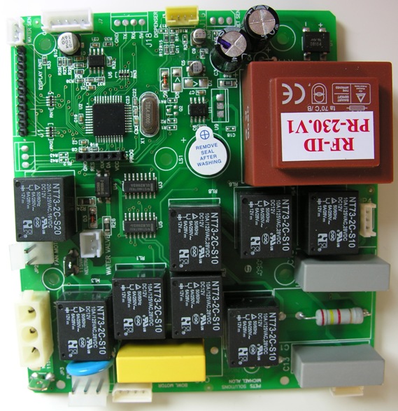
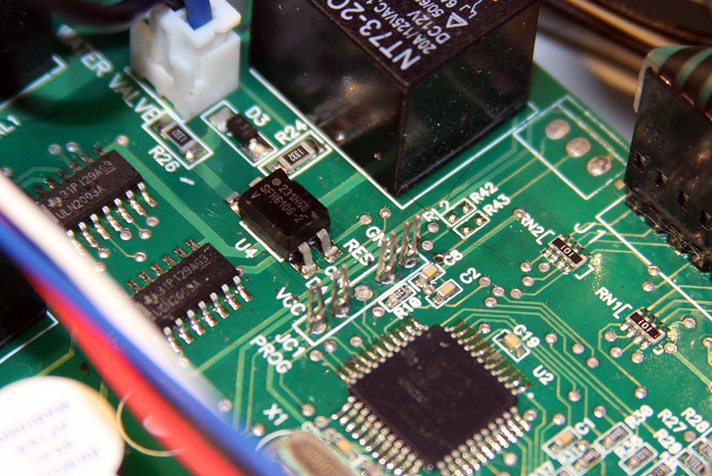
The controller board is attached to the front shell by four smaller screws. This is a photo of the controller board:
The photo looks like it's up-side-down, and in fact it is, but in this photo it matches the orientation of how it is mounted to the front shell. The component resembling a black stamp, designated U2 on the left top of the board is the micro controller. It is either a PIC16F877A or a PIC16F1939, both made by MicroChip. The 5-pin connector right below it, designated JC1 PROG, is the programming connector. This is the connector we will use to program new firmware into the micro controller. The 4 pads for non-mounted connector J18 are interesting to us as well. They are connected to the micro controller's built-in serial port, which is very useful for debugging information. I will write a separate page on how to connect this serial port.
The Programmer
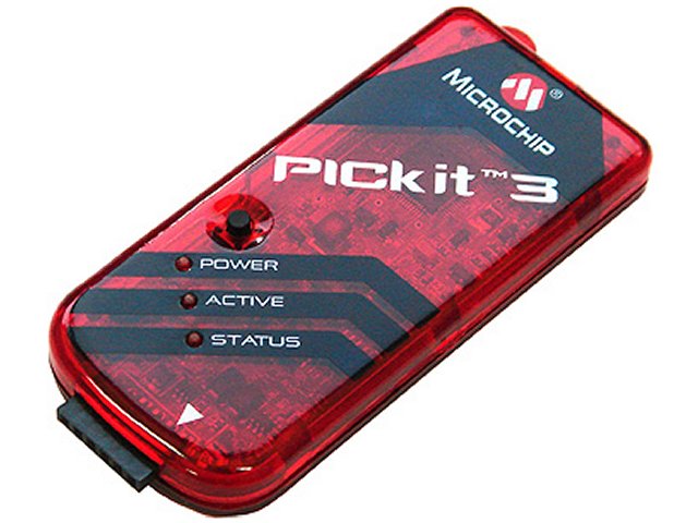
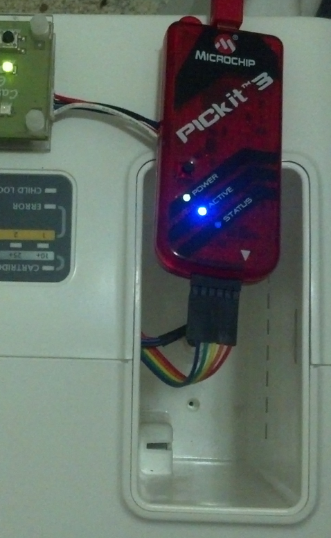
To reprogram the micro controller, you will require a special PIC programmer. You can use a MicroChip PICkit2 (as I'm using) or PICkit3 programmer, available for about $35.
https://raw.githubusercontent.com/CatGenius/catgenius/master/documentation/wiki/pickit3.jpg
A MicroChip ICD may work as well, but that would be a bit over-kill. A third party imitation programmer may work too, but it that case you're on your own. A PICkit programmer usually comes with a test target, which is nice to experiment with, but you won't be needed that for this project, so the $35 version without it will do.
The Cable
To connect the PICkit programmer to the controller board, a specially made cable is required because both connectors are not pin compatible. A connection table of which pin of the PICkit to connect to what pin of the controller board is shown below: PICkit:Controller, JC1 PROG: # = Name# = Name 1 = VPP/MCLR4 = RES 2 = VDD Target1 = VCC 3 = VSS (ground)5 = GND 4 = ICSPDAT/PGD2 = DA 5 = ICSPCLK/PGC3 = CLK 6 = AuxiliaryNot Connected
There are two options for making this cable: Modifying a pre-made cable, or soldering your own. In either case, you will need some break-off headers like the ones available here.
Using A Pre-Made Cable
For those of us clumsy around a soldering iron, using a pre-made cable may be a less messy solution. In any case, using a pre-made cable is arguably more reliable. Unless you're lucky enough to have one lying around, one can be obtained for less than USD $1 here.
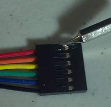
To modify the cable, you will need a jeweler's screwdriver or equivalent. Use the flat-end of the screwdriver to lift the plastic that is catcting the connector you wish to remove, then pull the wire back:
https://raw.githubusercontent.com/CatGenius/catgenius/master/documentation/wiki/cable_female_header_adjust_1.png https://raw.githubusercontent.com/CatGenius/catgenius/master/documentation/wiki/cable_female_header_adjust_2.png
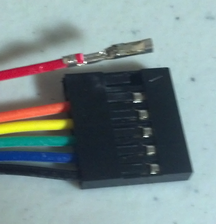
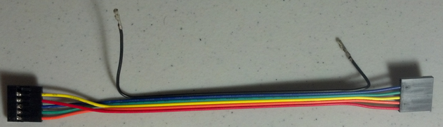
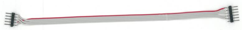
Only the wires on one end of the cable need to be adjusted. Your goal is for the cable to look like this:
https://raw.githubusercontent.com/CatGenius/catgenius/master/documentation/wiki/cable_prog.png
Now we need to adjust the cable so that it has male headers on both ends instead of female. Purchase some breakable headers like above, then adjust the plastic spacer with a pair of flat pliers so it is in the middle like this:
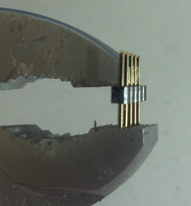
Make two male-to-male headers, one 5-pin for connecting to the CatGenie board, and one 6-pin for connecting to the PICkit 3. You can also remove the spare black wire by just pulling it off. After this has been done, your cable should look like this. Note that the red wire connects under the white triangle on the PICkit 3:
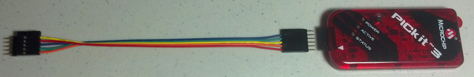
Attach the 5-pin end of the cable to the CatGenie board like below. When properly oriented, the yellow wire should go to GND and the orange wire to VCC:
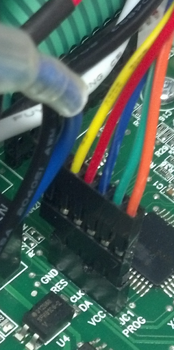
(Optional) In order to avoid having to open the shell everytime you wish to program your CG, feed the other end of the cable through the hole in the dispenser bay (Just like the I2C cable for the CartridgeGenius), like so:
Making Your Own Cable
This requires a bit of soldering, some break-off headers like shown above, and some ribbon-cable wire (Any old floppy/IDE drive cable should do).
When properly made, the cable should look like this on the front:
And like this on the rear:
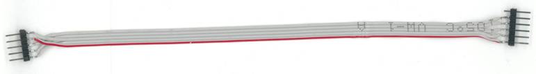
The 6-pin side is connected to the PICkit programmer, with pin one (the red lead) aligned to the end of the connector marked with a white triangle. The 5-pin side connected to connector JC1 of the CG120 controller board, with pin one (the end with the 3 grey wires) aligned to the end marked VCC. I recommend you to make this cable no longer that 20cm, 40cm at maximum, to prevent signal integrity problems.
Flashing
Please follow these instructions very carefully and exactly. Any deviation could result in a dead CatGenie box. If that does happen, it can usually be resolved by... following these instructions carefully and exactly ;).
Note that there is a stand-alone command line tool from Microchop called PK3CMD.EXE that is supposed to allow you to program with the PICkit 3, but it can and will kill your box.
DO NOT plug in your PICkit 3 before you have installed MPLAB, otherwise the wrong drivers might get loaded.
Preparation:
Obtain a PICkit 3
    There are several PICkit 3 kits available, including some with test boards, but the minimum you need is this: http://www.microchipdirect.com/productsearch.aspx?Keywords=PG164130
    If you're already ordering some parts from SparkFun and want everything in one bundle, the programmer is available on that site for USD $5 more than from Microchip: https://www.sparkfun.com/products/9973
Obtain or make a programming cable as outlined above
Download MPLab v8.89
Identify which microcontroller your CatGenie has: PIC16F1939 or PIC16F877A
Download the appropriate HEX file firmware based on your microcontroller
Steps:
Install MPLab
Run MPLab and configure it for your microcontroller
Power on your CatGenie
Connect the PICkit 3 to your CatGenie
Connect the PICkit 3 to your computer
Flash the new firmware using MPLab
Enjoy CatGenius!
Downloading MPLab
Download MPLAB v8.89 on Windows 7 32 or 64-bit. Other versions of MPLAB and Windows have been known to cause problems with flashing. In any case, the installer CD that came with my PICkit was corrupted, and yours likely is too.
Click this link to download MPLAB. Make sure it's v8.89. Microchip has been known to break parts of their software in newer releases.
Note that the download page contains some information about a new IDE called "MPLAB X". We haven't had a chance to try it out yet, so use at your own risk. If you do happen to get it working, we'd love to hear about it.
A list of all development tools available for download is here (May work if the v8.89-specific link does not).
Downloading CatGenie Firmware
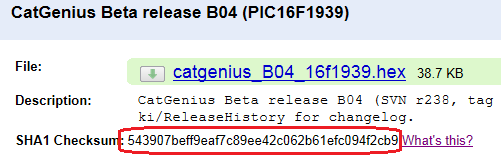
Determine the microcontroller in your CatGenius and download the appropriate HEX file from here.
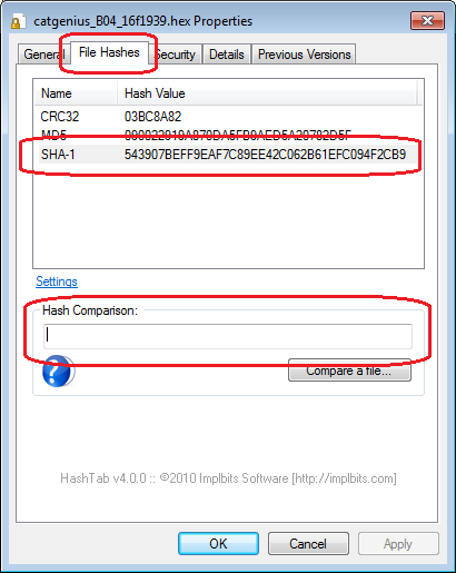
In this modern day and age you'd think that file corruption would not be an issue, but it still happens. To verify the HEX file is correct, you can compare the hash of your downloaded file with the hash displayed on the download detail page:
Several programs are available for Windows 7 that will check the hash for you. We recommend HashTab, available for download here.
CNET tries to trick you into either downloading something else, or downloading their "downloader", so be sure to click only the "Direct Download" link on the left of the page:
https://raw.githubusercontent.com/CatGenius/catgenius/master/documentation/wiki/hashtab_1.png
Install HashTab, then right-click on your Hex file in Windows Explorer and select the "File Hashes" tab:
https://raw.githubusercontent.com/CatGenius/catgenius/master/documentation/wiki/hashtab_2.png
You can then either visually compare the SHA1 value against the one listed on the download detail page, or copy and paste the value from the download page into Hash Tab for verification. Case does not matter.
Installing MPLAB
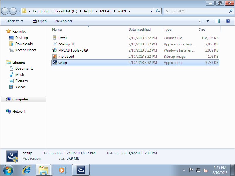
Once you have downloaded MPLAB, extract the ZIP file and run the setup program:
https://raw.githubusercontent.com/CatGenius/catgenius/master/documentation/wiki/mplab_inst_1.png
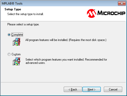
When you come to the "Setup Type" screen, select Complete (the default), and click Next:
https://raw.githubusercontent.com/CatGenius/catgenius/master/documentation/wiki/mplab_inst_2.png
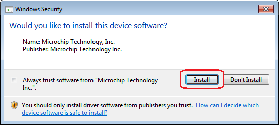
After the installation has completed, drivers will be loaded for the Microchip programmer suite. A warning dialog will be displayed. Click Install:
https://raw.githubusercontent.com/CatGenius/catgenius/master/documentation/wiki/mplab_inst_3.png
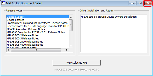
A dialog will be presented with various documentation available. Review it if you'd like. When you are done, click the X at the top-right corner to close the window:
https://raw.githubusercontent.com/CatGenius/catgenius/master/documentation/wiki/mplab_inst_4.png
Programming with the PICkit 3 in MPLAB
Start MPLAB IDE either via the icon on the desktop or via the Start menu. Select Configure / Select Device, make sure ALL is selected for the Device Family (the default), enter your full microcontroller name (PIC16F1939 or PIC16F877A) in the Device Name box, then click OK:
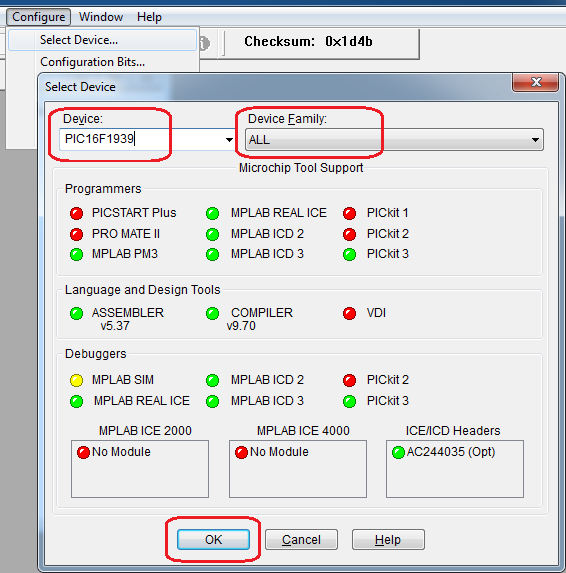
Select File / Import and browse to the HEX file appropriate for your microcontroller:
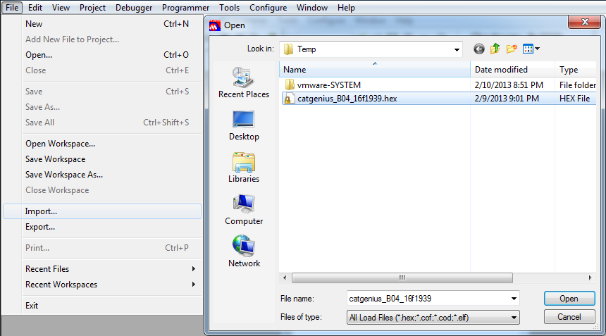
Power on your CatGenius (Attempting to program while the CG is turned off usually results in failure), connect the PICkit 3 to the CG via the programming cable, and plug the PICkit 3 into your computer via the USB cable. Select Programmer / Select Programmer / PICkit 3:
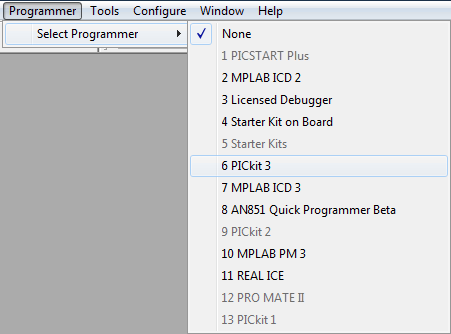
You should see a message that PICkit 3 is connected and the target device was detected:
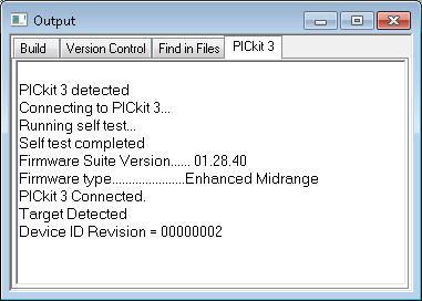
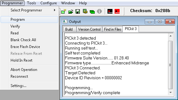
It's business time. Select Programmer / Program. An Output window will appear showing you the progress. After about 2 minutes you should see "Programming/Verify complete":
If programming failed or the PICkit 3 was not detected, re-read the directions to make sure you have not missed anything, check your cables, and try again.
If programming succeeded, you can disconnect the programming cable. Leaving it attached while using the CatGenie can cause sporatic behaviour.
Note that by default the CatGenius firmware displays no lights as it is in Mode 0 (Manual Mode - See the CatGenius User's Manual for details). To confirm it is working, press Select to change into another mode, or press Start to start the dry wash program.
Enjoy!
Older PICkit 2 Instructions
If you have a PICkit 2, use the following instructions: Start the PICkit application (not MPLab): Start menu -> Microchip -> PICkit 2 v2.11 In this program, first select the Midrange device family in the Device Family menu. Next, erase the chip by pressing the Erase button. This will also clear any HEX file you may already have loaded. Now import the HEX file that needs to be programmed: file -> Import Hex Finally, program the device by pressing the Write button. Optionally you may want to press the Verify button to make sure everything is written correctly.
Getting Dirty
WE HAVE NOT TRIED THIS; USE AT YOUR OWN RISK
If you're a true hacker and don't mind getting your hands dirty, you can build your own PIC programmer for just a couple of dollars. The pin-out is about the same as the PICkit 3, except pins 4 and 5 are reversed, and there is no LVP pin. If you're going to try this, then I'm assuming you can figure that out. Here is the link.
Caveats
Even though the box can be programmed unpowered, the result can be unstable. Problems can vary between an unstable box, erratic behaviour, the box loosing it's program or a combination of the three. The cause of this instability is a too-low supply voltage during programming when powering the CPU from the programmer.
Another known problem is the CPU being identified by the programmer as ID 0000, usually accompanied by verification errors after programming. This problem is most likely caused an error or a poor contact in the programming cable. One of the most common causes for a poor contact is a missing pin in the programming header on more recent controller boards. To make sure your controller has a missing pin too, remove the plastic header from the programming header and check if all pins are present. Below is a photo of a programming header with the plastic header removed, showing a missing pin.