How the water sensor works - CatGenius/catgenius GitHub Wiki
Introduction
One of the hardest parts to get right is the water sensor. It is fairly straight forward to get it to work, but getting it to work properly and under all circumstances is a whole different story. The main reason for this is that it is poorly designed. On this page I will explain how the water sensor works so you can identify and solve related problems. The water sensor is not an analogue water level measuring device. Instead it's a digital sensor that indicates whether the maximum water level has been reached. If the sensor is triggered, the box is full of water. But if the sensor is not triggered, there may still be water present. Quite a lot actually.
The light guide
The part most of us know as the water sensor is just a small part of the actual sensor, a translucent tuning fork shaped piece of plastic. I will call this part the light guide, because that's what it does. The water sensor works by means of refraction. The illustration below shows a photo of the light guide and the way it guides light in a dry condition.
https://raw.githubusercontent.com/CatGenius/catgenius/master/documentation/wiki/watersensor_dry.jpg
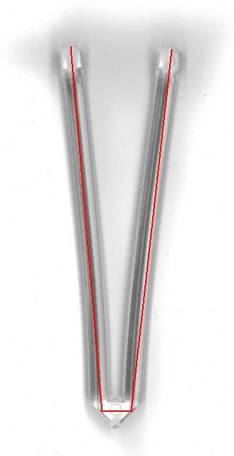
Positioned in the bottom of the processing unit, above the top left end of the light guide in this illustration, is an infra-red detector. Next to it, above the top right end is an infra-red emitter. When the light guide dry, the air/plastic refractive index will make the angled surfaces on the bottom side reflect the emitted infra-red sideways and back upward. However, if these angled surfaces are submerged in water, the water/plastic refractive index will not reflect light under that angle anymore.
https://raw.githubusercontent.com/CatGenius/catgenius/master/documentation/wiki/watersensor_wet.jpg
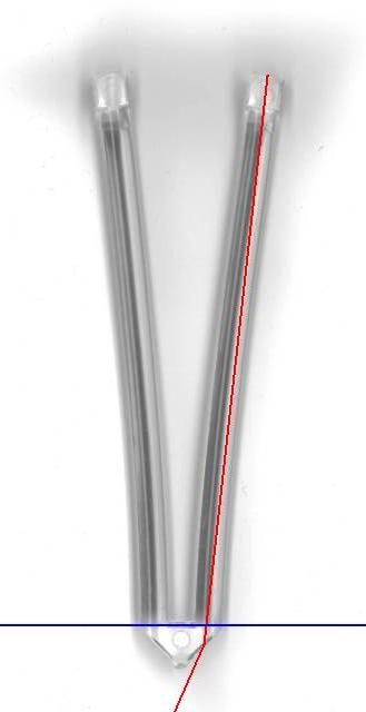
Instead, the emitted infra-red leaves the light pipe and can no longer be detected on top left end. You can easily validate this using the light guide from your box, a flashlight and a glass of water. So far no problem.
The electronics
At the electronics things are starting to go wrong. Below is a diagram I drew from the board.
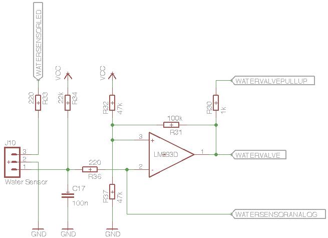
Please note that the infra-red emitter is connected between pin 2 and 3 of J10 and that the infra-red detector is connected between pin 1 and 2 of the same connector. The signals coming from and going to the micro controller are named:
- WATERSENSORLED
- WATERVALVEPULLUP
- WATERVALVE
- WATERSENSORANALOG
A note worthy detail is that the signal WATERVALVE is directly connected to the water valve relay driver, as well as to a I/O pin of the micro controller.
The diagram is basically a schmitt-trigger, an amplifier with positive feedback to obtain a hysteresis. In this case the signal is fed to the negative input to have in inverted for the water valve.
The first signal, WATERSENSORLED, is very straight-forward. The corresponding micro controller I/O pin is a permanent output, switching on and off the infra-red emitting LED. How the LED is controlled will be explained further down on this page.
The function of the second signal, WATERVALVEPULLUP, was a bit unclear to me. When I was measuring the output level of the OpAmp, I noticed that it was either 0v or 2.5v when the micro controller's WATERVALVEPULLUP pin was in tristate. Sourcing it high by the micro controller pulled the 2.5v up to a nice 5v. I figured that the OpAmp wasn't able to source all the way up to 5v and it might need a pull-up resistor for that, in this case R30. It puzzles me why they used a micro controller output for that instead of pulling it straight to Vcc. In CatGenius the corresponding micro controller I/o pin is a permanent output, always sourcing a high signal. Please let me know if I'm wrong here!
The third signal, WATERVALVE, represents the actual detection state. It is connected to both a micro controller I/O pin and the water valve relay driver. I have made the corresponding micro controller pin a permanent input, monitoring the water sensor circuit operating the water valve.
The fourth signal, WATERSENSORANALOG, is a strange one. I allows measurement of the analogue photo diode voltage, but I have no evidence the original CG120 firmware actually does this. It is not very likely the original CG120 uses this signal because when this pin is configured as an analogue input pin, two I/O pins connected to two of the LEDs will change into analogue inputs as well. The original firmware may alternate these functions run-time, but that's very unlikely. Perhaps this is a residual measurement pin, used during development.
How it works together
When this circuit is active, the water sensor has full control over the water valve: If no water is detected, the circuit will open the water valve automatically until water is detected. When water is detected, the water valve will be closed, for as long water is detected. I call this feature auto-filling. It keeps the box a topped up at the maximum level fully automatically and it inherently prevents it from flooding as well. The micro controller can detect the presence of water by monitoring the the WATERVALVE signal. If the circuit opens the valve, no water is detect. If it doesn't, water is detected. Most of the time we don't want the box to be filled with water (automatically). That's where the WATERSENSORLED signal comes in. If no water is reflected in the light guide, the sensor circuit will conclude the presence of water and the water valve will be closed. So if no water is desired, but no water is present, switching off the WATERSENSORLED signal will have exactly the same result. If the water sensor needs to be read while no water is desired a little trick is needed. In this case the WATERSENSORLED signal has to be switched on for a brief moment. This moment has to be brief enough to make sure the water valve doesn't open. It should even be brief enough to prevent the water valve relay to tick, which would lead to mechanical wear. But it has to be long enough for the photo diode to detect a reflection in the light guide. Originally I tuned this time to 300 us. In later revisions the algorithm waits for this reflection for a maximum time of 2 ms, shorter if the reflection is detected earlier.