ALU - CarlosCraveiro/RISCV_based_processor GitHub Wiki
The arithmetic logic unit(ALU) is the switching circuit whose function is to perform arithmetical operations on hardware. This operations can be sum, subtraction or multiplication, for example. In this project, the ALU model used has 5 functionalities: integer sum, integer subtraction, logical AND, logical OR and set if less than(SLT).
Description of operations
Sum is implemented via digital logic of full adders, and subtraction is basically summing a number to the other's two's complement(it's negative value). Logical AND and OR basically need AND and OR gates for the N bits two numbers. SLT sets true if the second number is less than the first, so it functions basically by subtracting two numbers and verifying if the result is less than 0 or greater than/equal to 0. To choose between this 5 functions, 3 control bits will be needed - named ALUControl[2:0]
The following tables describe the opcodes of the 5 functions of ALU based on ALUControl[2:0] and the result of SLT function.
| Opcode | Operation |
|---|---|
| 000 | A + B |
| 001 | A - B |
| 010 | A and B |
| 011 | A or B |
| 100 | - |
| 101 | SLT |
| 110 | - |
| 111 | - |
- Table that describes the operations of ALU according to opcode(
ALUControl[2:0])
| A >= B | A < B |
|---|---|
| 00000000 | 00000001 |
- Table that describes the result of SLT function given the inputs A and B
This means that, performing the subtraction A-B, the signal bit of the result is 1 if negative(A < B) and 0 if positive/zero (A >= B). This suggests that the A-B operation holds the information about the SLT result, being used for it's implementation. The only adaptation to be made is to zero-extend the bit signal to N output bits - which is why SLT operation uses a Zero-Extension module.
ALU Schematic
The following image shows a schematic of all the ALU operations implementation on hardware:
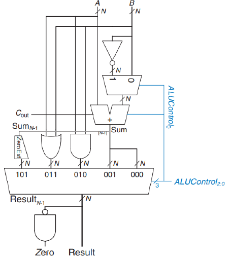 3. Figure with ALU Schematic. Source: Digital Design and Computer Architecture - RISC-V Edition(Sarah Harris and David Harris)
As it can be visualized on the schematic, the inputs are only ALUControl that controls the muxes and determines the operation and the SrcA and SrcB values to operate on. The outputs are only ALUResult and Zero, corresponding to the result of operation and a flag to indicate if the result is zero, repectively. The schematic show the input and output buses as N-bits wide, as the impementation on the Verilog code(that is made via a parametried module) - but the instantiation of the ALU module on the processor top module will use an ALU of 16 bits.
Code modularization and description
The top module of ALU can be found on ALU.v, which basically instantiates the modules and switching circuits found on the schematic: a zero-extension module is used for the SLT operation, a half-adder(native from Verilog) is used by sum and subtraction, the NOT gate is implemented via a two's complement module, the AND and OR gates are native from Verilog. Additional wires are declared to route the connections on the schematic, being them:
 wire [(WIDTH - 1):0] SrcB_2comp;
 wire [(WIDTH - 1):0] SrcB_var;
 wire [(WIDTH - 1):0] Sum;
 wire [(WIDTH - 1):0] zExtended;
 wire [(WIDTH - 1):0] OrOperation;
 wire [(WIDTH - 1):0] AndOperation;
 wire [(WIDTH - 1):0] DoNothing;
The SrcB_2comp wire receives the twos complement of SrcBinput, whileSrcB_varreceives the chosen variable after the mux that choses betweenSrcBandSrcB_2comp. The Sumwire receives the result of the full adder(being that the sum or the subtraction, depending onSrcB_var being the original B or the twos complement). The zExtended wire receives the zero extension of the signal bit of the result, while OrOperation and AndOperation receive the operations that their names suggest. DoNothing only exists to connect to the unrouted ports of the 8x8 mux(notice the table that describes the ALU operations do not correspond to any operation) and is not routed to any other wire or input, meaning Verilog shall define it as a high-impedance value.
The other files are:
-
The muxes are found on
muxes.v, that implements muxes 2x2,4x4 and 8x8(only 2x2 and 8x8 are actually used on theALU.v). -
The zero extend can be found on
N_zero_extend.vwhich is parametrized to receive a 1-bit signal and zero extend it(extension implemented via a generate block) to N(a given parameter) bits. -
The two's complement module can be found on
two_complement.v, which basically negates the input and sums one(what is the definition of two's complement)