Solar Panels - CalgaryToSpace/CTS-SAT-1-Wiki GitHub Wiki
The Solar Panels
The Solar Panels are what power our satellite while it's in sunlight. The following are its respective GitHub Repos:
- https://github.com/CalgaryToSpace/CTS-Solar-Panel-Load-Tester
- https://github.com/CalgaryToSpace/CTS-SAT-1-Solar-Panels
Powering the Solar Panels
The EPS uses maximum power point tracking (MPPT) to operate the solar panels at their maximum power point. The maximum power point is determined by a P-V (power-voltage) graph.
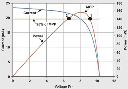
Photo credit: https://www.mouser.ca/applications/solar-panel-power-tracking/
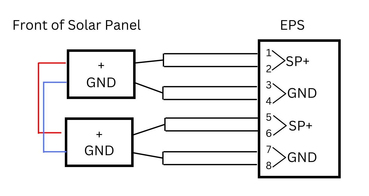
Each COTS solar panel has two power connectors, each with a power pin and a ground pin (4 pins total). They each connect to an 8-pin MPPT connector on the EPS. To facilitate connection, each wire from the solar panel connector will diverge into two wires.
1.25 U Solar Panels (Second Revision)
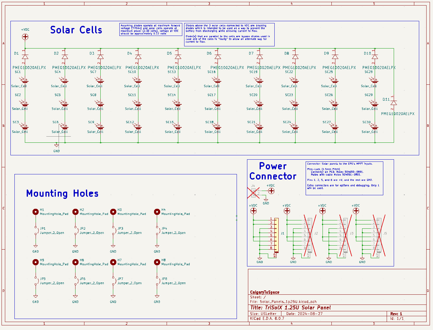
This schematic shows the electrical design for a 1.25U Solar Panel System, created using KiCad. The circuit integrates solar cells, blocking diodes, mounting holes, and a power connector.
-
Solar Cells (Top Section): Purpose: The solar cells convert sunlight into electrical energy. Details: Solar cells are connected in series, allowing the output voltage to add up across each cell. Groups of cells (like SC1 to SC3, SC4 to SC6, etc.) are grouped into individual "strings." Total voltage produced depends on the number of cells in series and the sunlight intensity.
-
Blocking Diodes: Purpose: Prevent reverse current from flowing back into the solar cells when they are not generating power (e.g., during nighttime or shaded conditions). Details: Diodes (D1 to D11) are placed in series with each solar cell string. These diodes block reverse current to protect the solar cells and improve system efficiency. Each diode has a small voltage drop (~0.2 V for Schottky diodes like PMEG1020AELPX) which is accounted for in the system design.
-
Power Connector (Right Section): Purpose: Provides the connection interface between the solar panel and the external system (e.g., battery or MPPT charge controller). Details: The connector uses a Pico-Clasp model with labeled pins (+VDC and GND). Only one output connection is used at a time to ensure simplicity and avoid confusion.
-
Mounting Holes (Bottom Section): Purpose: Mechanically secure the solar panel onto its enclosure or structure. Details: The holes (H1 to H8) correspond to physical locations on the panel for mounting. Electrical connections for the holes are tied to ground (GND), likely for grounding the system during assembly.
1.25 U Solar Panels (Third Revision)

In the third revision, we switched over to the KXOB25-05X3F-TB model of the solar cells. We switched over from the Tri-SolX Cells since it's more durable and cost efficient.
Load Tester Circuit
The purpose of a load tester circuit is to evaluate the performance and reliability of a power supply or electronic system under varying load conditions. By simulating different load scenarios, the circuit ensures the device can maintain stable operation, deliver the required voltage and current, and handle fluctuations effectively. Two design approaches were considered for the load tester: one utilizing a potentiometer-based design for simplicity and manual control, and another employing an operational amplifier and MOSFET-based design for greater precision and dynamic load adjustment.
Ope-Amp and MOSFET based Load Tester
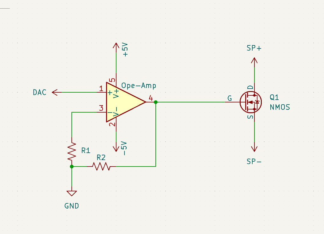
An op-amp-based electronic load is a circuit used to simulate and control a precise load current for testing power supplies, batteries, and voltage regulators. It works by using an operational amplifier (op-amp) to regulate the gate voltage of an NMOS transistor, which acts as a variable resistor. A reference voltage, typically provided by a DAC, sets the desired load current. The op-amp compares this reference voltage with the feedback voltage across a sense resistor, which is proportional to the load current. If the feedback voltage is lower than the reference, the op-amp increases the gate voltage, allowing more current to flow through the NMOS transistor until the feedback matches the reference. This closed-loop operation ensures the load current remains stable and precisely controlled, making the circuit ideal for dynamic load simulations and testing in power electronics applications.
Solar Panel Simulation in LT Spice

The image above shows a basic circuit that can be built on Lt Spice to simulate a solar panel. The basics of the circuit are a current source, two resistors, and a diode. There are several parameter that must be specified to simulate a solar panel:
-Rs, this represents the internal resistance of the solar panel.
-Rsh, this represents the leakages of the diode since LT Spice assumes diodes are ideal.
-Iph represents the current generated by the solar panel.
-Io and a_n are based on the properties of diode.
There is more detail about the theory involved in the theory behind simulating a solar panel in the following youtube video: https://www.youtube.com/watch?v=uV_z1ptufa4&t=2s
These parameters are not easily found about solar panels, however there are algorithms to find these values based on readily avaible values found in solar panel datasheets. More information about such a algorithm and the specifics of using LT spice to simulate a solar panel are found in this video: https://www.youtube.com/watch?v=ox0UtYe4owI&t=240s
Stack and Not Stack Solar Panels
| Pin Header Side | |
|---|---|
| MPPT CH4 | Connector on EPS located on Nadir |
| Non-Pin Header Side | |
|---|---|
| MPPT CH1 | Connector right underneath solar panel on "non-pin header side" |