TO DO: Nicolette Ephys Box setup - BrendonWatsonLab/Digital-Homecage GitHub Wiki
Carries a 5V(?) signal from labjack to light relay board to turn on/off visible LED's based on configuration found in labjackcontroller.ino(TO DO LINK THIS)
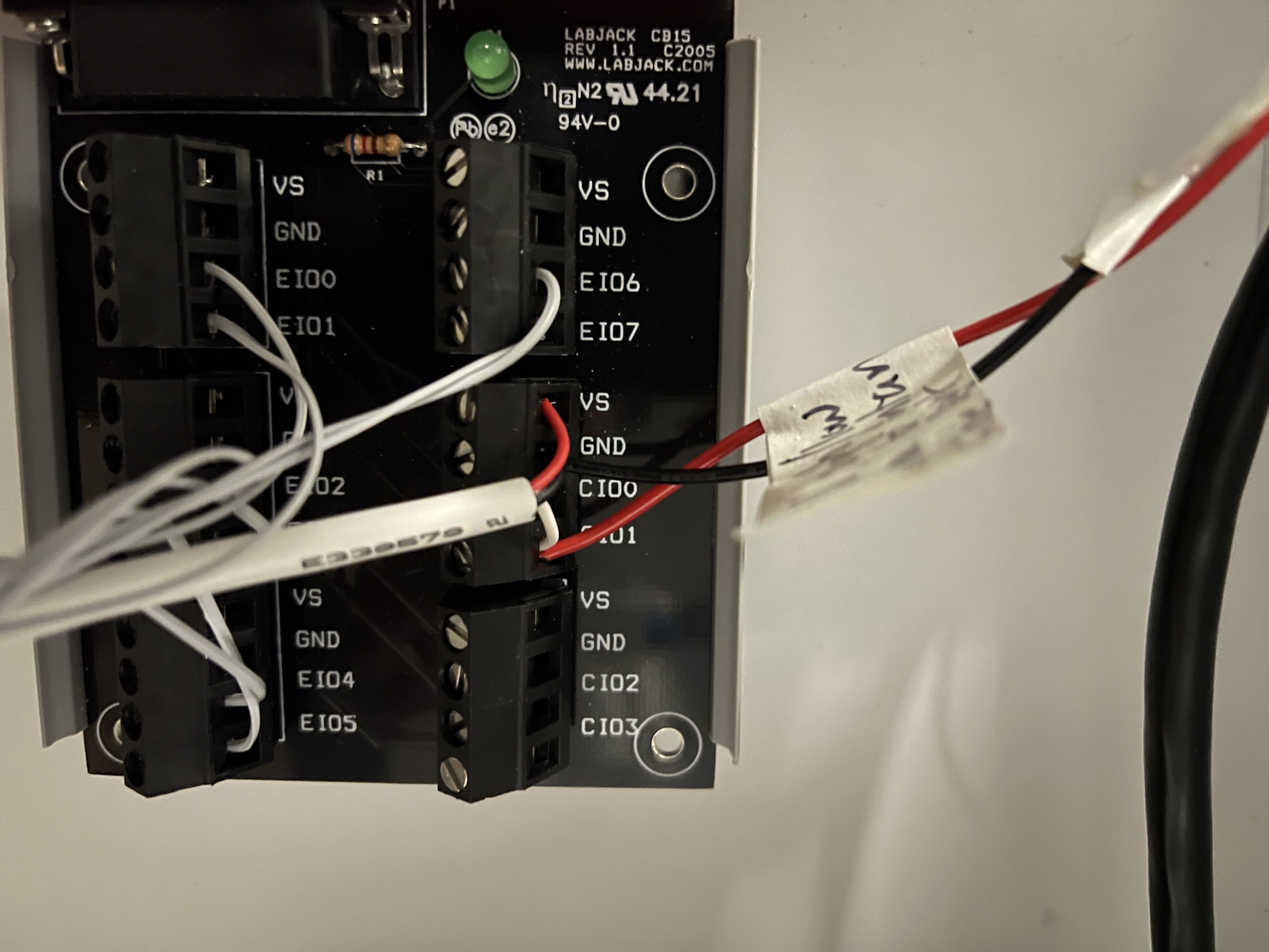
From the labjack CB15 Terminal Board (addon board pic below):
VS: Red wire from cable connecting Labjack CB15 "VS" on middle right block to "DC+" on the light relay board.
GND: Black wire from cable connecting Labjack CB15 "GND" on middle right block to "DC-" on the light relay board.
CIO0: Empty
CIO1: White wire from cable connecting Labjack CB15 "VS" on middle right block to "IN" on the light relay board.
Carries a 5V(?) signal from an individual labjack to intan in order to see when the lights are on/off in the box for purposes of circadian alignment of Labjack data acquistion. Note: When the 5V(?) signal turns OFF, the visible LED's turn ON.
Use a pair of twisted twisted wires. One carries a 5V(?) pulse to one of the digital IN pins on the intan board. The other is GND and it plugs into one of the GND pins in the Intan board.
From the labjack CB15 Terminal Board (addon board pic below):
GND: The same GND port will connect one wire (from a twisted pair of wires) to any "GND" pin on the Intan.
CIO1: The same CIO1 port will connect one wire (from the same twisted pair of wires as GND above) to any "Digital In" pin on the Intan. Keep track of the box this wire comes from and which Digital In on Intan it screws to.
CIO0: Empty
Wiring that connects the basler camera to INTAN recording system.
-
On the wire which connects the camera to the INTAN, find the end with the exposed wires.
a) Using a wire stripper, remove ~6-12 in of the beige cover/shell to expose the metal mesh underneath.
b) The exposed metal mesh can be pulled back and cut away. Do this away from any electronics to avoid metal debris from causing shorts.
c) The exposed clear plastic can then be pulled back and cut away also. You should just have the different colored wires now.
-
Keep the brown, white, and green wires. Cut off the other exposed wires.
-
Solder the tips of the brown, white, and green wires.
Wire Color Key:
a) Brown wire (can be labelled as the "a" wire; ex: BB##a): Takes 5V from pulse generator to the camera for the start/stop signal which segments videos down to the length of the pulse output by pulse generator.
This wire is Line 3 in PYLON software.
TODO: Solder male ____ to the end of the wire to make connecting easier.
b) Green wire (can be labelled as "b" wire; ex: BB##b ): Connects camera to an INTAN digitial in port. Gives INTAN the timestamps of each frame from the camera.
This wire is Line 4 in the PYLON software.
c) White wire (can be labelled as "c"; ex: BB##c): Connects the camera to a GROUND port on the INTAN. (Need to clarify this-> Pin 6 hardware. Functions as GND for direct-coupled GPIO)
Cameras must be properly set up with Basler Pylon before they can be used with streampix. If you fail to do this, you will have SEVERE AND EXPERIMENT RUINING camera issues when cameras are unplugged/camera computer power is cycled.
- Follow steps 1 and 2 in the "1) DOWNLOAD BASLER PYLON FIRST:" found in the "Setting up Streampix" section of the wiki to install the correct version of Basler Pylon.
NOTE: PYLON is extremely annoying with regards to how it handles mouse scroll wheel inputs. You could change settings without even noticing while scrolling down a page. DO NOT USE MOUSE SCROLL WHEEL WHILE CHANGING PYLON SETTINGS.
Another annoyance with pylon is that the camera must be toggled open to change settings, but the camera must NOT be continuously shooting. Toggle Open means the camera is active/on in basler pylon. Continuously Shooting means capturing or "seeing" new frames. If you move your hand in front of the camera, you'll see it when the camera is Continuously Shooting. To change camera settings. Toggle the camera OPEM with the pylon gui (top left button, under file usually), but DO NOT select Continuous Shooting (Video Camera Button). After you change the settings you want, you can enable Continuous Shooting to see the changes you made. SEE THESE VIDEOS MADE BY LEZIO. WALK THROUGH THE VIDEOS IN NUMBERED ORDER (Most of the settings shown in these vids are correct)
Overview: We'll change the camera settings below, but that will only change the settings currently. If the camera is unplugged or the camera PC power is unplugged, it will reset to factory default settings. So after changing settings to what you want, we will then save the settings in a User Set (a configuration containing the settings we want) and then select this new User Set as the default User Set, so that this new user set is loaded by default if the camera is turned off/on or becomes unplugged.
Camera Settings to change (only change the settings mentioned here, and change them to the values mentioned here. Some settings wont be changed at all. Also, some versions of pylon have settings moved to other tabs :():
NOTE: You will have to manually change these setting for each camera. Complete all the steps below for one camera, then move to the next one.
Binning Horizontal Mode: Average
Binning Horizontal: 2
Binning Vertical Mode: Average
Binning Vertical: 2
This will should change the resolution (width and height in image format control) to 640x512. If the resolution is not at 640x512, grab the width and height sliders and drag them all the way to the right.
If you can't change the binning modes, make sure you DON'T have Continuous Shot active.
Shutter Mode: Global
Exposure Auto: Off
Exposure Mode: Timed
Exposure Time: 5000.0us (This changes the sensor exposure, but you will have to also play with the lens exposure so that it looks "right" with the box lid close. Err on the side of too bright, vs. not bright enough. The lens exposure is hard to standardize across all the boxes.)
Sensor Readout Mode: Normal
Enable Acquisition: Check this Box/Select this box
Acquisition Frame Rate: 30 (it will change to slightly above 30)
Line selector: Line 4
Line mode: Output
Line Source: Exposure Active
Line Inverter: Box is CHECKED
4) User Set Control Tab in pylon: Allows you to save these settings, as well as control the default settings that the camera loads when it's unplugged/re-plugged.
To save the changes I made above to User Set 1 FOR THIS CAMERA ONLY.
- User Set Selector: User Set 1
- User Set Default: User Set 1
- User Set Save: Execute
- User Set Load: Execute
First Follow instructions here to activate the USB dongle key and streampix software. Streampix license MUST be activated before you can actually see the camera feed on streampix software:
Then, follow Lezio Bueno's tutorials on setting up the streampix environment: https://drive.google.com/drive/folders/1UsHu8wqjX_w_g1SUQhUc7NcvFjpvGYbF?usp=sharing