Audio adapter board - BleepLabs/Arduino-Light-And-Sound GitHub Wiki
The audio adapter board has the ability to input and output stereo audio at a 44.1kHz sample rate and 16 bits of resolution, aka “CD quality’ sound. The board contains an audio codec chip that is able to input and output analog signals much faster than the Teensy could on its own. Even devices as fast as phones rely on other specialized chips like this to specific tasks much more quickly than the main processor could do on its own.
Installing
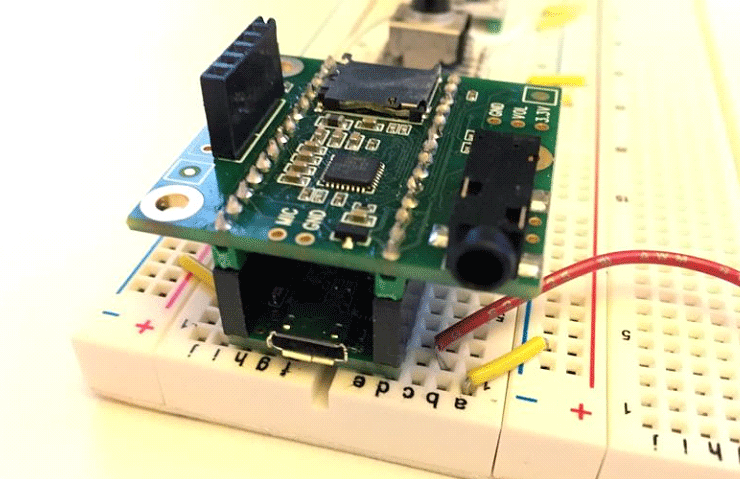
To install the audio adapter, first remove the USB cable from the Teensy.
Make sure the audio board is installed with the 1/8' jack on the same side as the USB jack and that all the pins are lined up. If it is hanging over one side or if it’s backwards you can damage the chips on the audio board.

You can remove the adapter board while the Teensy is on. It won’t hurt anything but you’ll need to reset the Teensy to get audio working again. The LED in the top right corner of the Teensy will light up and flicker a bit when the audio adapter is in use.
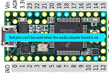
Some of the Teeny's pins are used to communicate with the adapter board so we can’t use them to do other things. (There are some caveats to that when using SPI or I2C but we'll talk about that later.)

Inputs and Outputs
The jack on the audio adapter board is a stereo output intended for headphones but it can be used with anything. Don't use a mono plug with it though has you'll get a clicking sound.
The device also has a line level input and output an a microphone input.
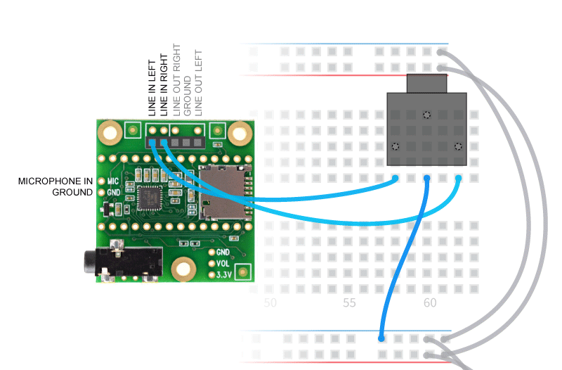
To use the line in simply connect it to a jack as shown.

The mic input can be used for simple electret or piezo elements. Just connect them between the two connections. Polarity generally doesn't matter.
Code setup
To use this board and setup the inputs and outputs to do some extra things in setup. Here's a full example.