Teensy - Autonomous-Motorsports-Purdue/Electrical_Documentation GitHub Wiki
Teensy (4.0)
The Teensy 4.0 is where active development is being done
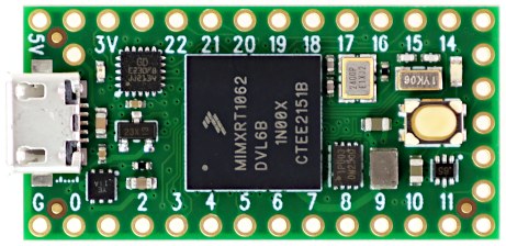
Specifications
- ARM Cortex-M7 at 600 MHz
- Float point math unit, 64 & 32 bits
- 1984K Flash, 1024K RAM (512K tightly coupled), 1K EEPROM (emulated)
- USB device 480 Mbit/sec & USB host 480 Mbit/sec
- 40 digital input/output pins, 31 PWM output pins
- 14 analog input pins
- 7 serial, 3 SPI, 3 I2C ports
- 2 I2S/TDM and 1 S/PDIF digital audio port
- 3 CAN Bus (1 with CAN FD)
- 32 general purpose DMA channels
- Cryptographic Acceleration & Random Number Generator
- RTC for date/time
- Programmable FlexIO
- Pixel Processing Pipeline
- Peripheral cross triggering
- Power On/Off management
Additional documentation can be found at https://www.pjrc.com/store/teensy40.html
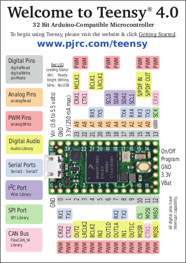
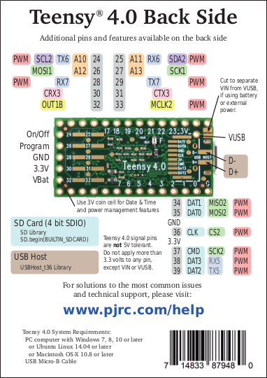
Pinout
Software
PlatformIO (USED BY AMP)
- PlatformIO IDE is a cross platform development environment with many advanced features. Windows, Linux and Macintosh are supported.
Arduino IDE + Teensyduino
- Arduino's IDE software with the Teensyduino add-on is the primary programming environment for Teensy. On Windows, Linux and old Macs, Arduino is installed first and then the Teensyduino installer adds Teensy support to the Arduino IDE. On newer Macs, an all-in-one download is provided. Teensyduino includes a large collection of libraries which are tested and optimized for Teensy. Other libraries may be installed manually or by Arduino's library manager.
Visual Micro
- Visual Micro allows use of Microsoft Visual Studio to program Arduino compatible boards, including Teensy. Only Windows is supported. Visual Micro is commercial paid software.
PlatformIO
- PlatformIO IDE is a cross platform development environment with many advanced features. Windows, Linux and Macintosh are supported.
CircuitPython
- CircuitPython provides a .HEX file which you program onto Teensy 4.0 using Teensy Loader. Then Teensy appears to your computer as a USB disk, where copy or save your Python code. CircuitPython does not fully support all of Teensy 4.0's hardware.
Digital Pins
Digital Input Pins
- Digital pins may be used to receive signals. Teensy 4.0 pins default to INPUT most with a "keeper" resistor. Teensy 4.0 pins accept 0 to 3.3V signals. The pins are not 5V tolerant. Do not drive any digital pin higher than 3.3V.
Input Pullup / Pulldown / Keeper Resistors
- All digital pins have optional pullup, pulldown, or keeper resistors. These are used to keep the pin at logic HIGH or logic LOW or the same logic level when it is not being actively driven by external circuity. Normally these resistors are used with pushbuttons & switches. The pinMode function with INPUT_PULLUP or INPUT_PULLDOWN must be used to configure these pins to input mode with the built-in resistor.
Pin Change Interrupts
- All digital pins can detect changes. Use attachInterrupt to cause a function to be run automatically. Interrupts should only be used for clean signals. The Bounce library is recommended for detecting changes on pushbuttons, switches, and signals with noise or mechanical chatter.
Digital Output Pins
- All digital pins can act at output. The pinMode function with OUTPUT or OUTPUT_OPENDRAIN must be used to configure these pins to output mode. The digitalWrite and digitalToggle functions are used to control the pin while in output mode. Output HIGH is 3.3V. The recommended maximum output current is 4mA.
Pulse Width Modulation (PWM)
- 31 of the digital pins support Pulse Width Modulation (PWM), which can be used to control motor speed, dim lights & LEDs, or other uses where rapid pulsing can control average power. PWM is controlled by the analogWrite function. 19 groups of PWM can have distinct frequencies, controlled by the analogWriteFrequency function.
Slew Rate Limiting
- This optional feature greatly reduces high frequency noise when long wires are connected to digital output pins. The rate of voltage change on the pin is slowed. The extra time is only nanoseconds, which is enough to lower undesirable high frequency effects which can cause trouble with long wires.
Variable Drive Strength
- The output impedance of each digital output may be controlled in 7 steps, ranging from 150 ohms (weakest) up to about 21 ohms (strongest).
Adjustable Output Bandwidth
- Digital output bandwidth is also programmable, in 4 steps: 50, 100, 150 and 200 MHz.
LED Pin
- Pin 13 has an orange LED connected. The LED can be very convenient to show status info. When pin 13 is used as an input, the external signal must be able to drive the LED when logic HIGH. pinMode INPUT_PULLUP should not be used with pin 13.
Analog Pins
Analog Inputs
- 14 pins can be used an analog inputs, for reading sensors or other analog signals. Basic analog input is done with the analogRead function. The default resolution is 10 bits (input range 0 to 1023), but can be adjusted with analogReadResolution. The hardware allows up to 12 bits of resolution, but in practice only up to 10 bits are normally usable due to noise. More advanced use is possible with the ADC library.
Analog Range
- The analog input range is fixed at 0 to 3.3V. On Teensy 4.0, the analogReference() function has no effect. The analog pins are not 5V tolerant. Do not drive any analog pin higher than 3.3 volts.
Analog Comparators
- These comparators allow an analog signal to be converted to digital, with a precisely defined voltage threshold for logic low versus high.