Electrical Theory - Autonomous-Motorsports-Purdue/Electrical_Documentation GitHub Wiki
Electrical Theory Overview
This document is the aggregated electrical theory knowledge relating to the kart
Amplifier
The first stage of the amplifier is a low pass filter that will average the voltage from the PWM signal from the MCU to make it appear as if it is an analog waveform from 0 to 3.3v.
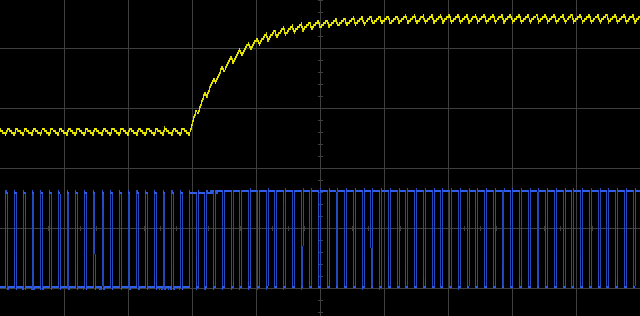
The next stage is to bring this pseudo-analog 0 to 3.3v throttle control signal to the 0 - 12v level that is needed for the motor controller. This is a standard non-inverting amplifier which will give a gain of 1 + Rf/R2.

Level Shifters
This circuit takes in the 0 to 3.3v PWM signal from the MCU (for servo steering motor) and scales it to a 0 to 12 volt signal. This is because the servo motor operates at a 12 volt logic level.
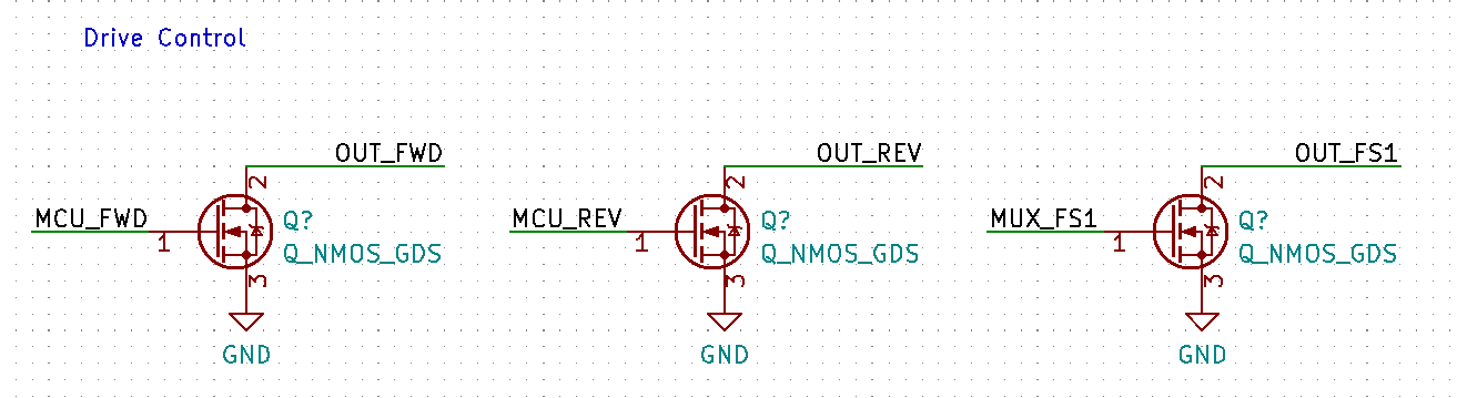
These next components are all transistors (switches) that are used to enable the motor controller and set it to the proper mode - forward or reverse.
Note that all transistors have the output connected to what appears to be an open circuit. In actuality, these pins are connected to a pull-up resistor in the motor controller that will nominally keep these inputs high whenever the MCU control signal is not asserted (transistor turned off).
When the MCU control signal is asserted, the transistor is turned on and the voltage will be shorted to ground.
General Electrical Tips
- When wiring up the cart batteries, ensure that the energized leads/wires do not make contact with any other conductive surface. This can lead to the batteries shorting out through the metal in the cart and will causes sparks.