Arduino Due (Legacy) - Autonomous-Motorsports-Purdue/Electrical_Documentation GitHub Wiki
Overview
No more active development is being done with the Arduino DUE! See the Teensy Wiki Page for information on the microcontroller used in active development.
The Arduino Due is a microcontroller board based on the Atmel SAM3X8E ARM Cortex-M3 CPU. It is the first Arduino board based on a 32-bit ARM core microcontroller. It has 54 digital input/output pins (of which 12 can be used as PWM outputs), 12 analog inputs, 4 UARTs (hardware serial ports), a 84 MHz clock, an USB OTG capable connection, 2 DAC (digital to analog), 2 TWI, a power jack, an SPI header, a JTAG header, a reset button and an erase button.

Warning: Unlike most Arduino boards, the Arduino Due board runs at 3.3V. The maximum voltage that the I/O pins can tolerate is 3.3V. Applying voltages higher than 3.3V to any I/O pin could damage the board.
The board contains everything needed to support the microcontroller; simply connect it to a computer with a micro-USB cable or power it with a AC-to-DC adapter or battery to get started. The Due is compatible with all Arduino shields that work at 3.3V and are compliant with the 1.0 Arduino pinout.
The Due follows the 1.0 pinout:
- TWI: SDA and SCL pins that are near to the AREF pin.
- IOREF: allows an attached shield with the proper configuration to adapt to the voltage provided by the board. This enables shield compatibility with a 3.3V board like the Due and AVR-based boards which operate at 5V.
- An unconnected pin, reserved for future use.
Pinout
 Download the full pinout diagram as PDF here.
Power
The Arduino Due can be powered via the USB connector or with an external power supply. The power source is selected automatically.
External (non-USB) power can come either from an AC-to-DC adapter (wall-wart) or battery. The adapter can be connected by plugging a 2.1mm center-positive plug into the board's power jack. Leads from a battery can be inserted in the Gnd and Vin pin headers of the POWER connector.
The board can operate on an external supply of 6 to 20 volts. If supplied with less than 7V, however, the 5V pin may supply less than five volts and the board may be unstable. If using more than 12V, the voltage regulator may overheat and damage the board. The recommended range is 7 to 12 volts.
The power pins are as follows:
- Vin. The input voltage to the Arduino board when it's using an external power source (as opposed to 5 volts from the USB connection or other regulated power source). You can supply voltage through this pin, or if supplying voltage via the power jack, access it through this pin.
- 5V. This pin outputs a regulated 5V from the regulator on the board. The board can be supplied with power either from the DC power jack (7 - 12V), the USB connector (5V), or the VIN pin of the board (7-12V). Supplying voltage via the 5V or 3.3V pins bypasses the regulator, and can damage your board. We don't advise it.
- 3V3. A 3.3 volt supply generated by the on-board regulator. Maximum current draw is 800 mA. This regulator also provides the power supply to the SAM3X microcontroller.
- GND. Ground pins.
- IOREF. This pin on the Arduino board provides the voltage reference with which the microcontroller operates. A properly configured shield can read the IOREF pin voltage and select the appropriate power source or enable voltage translators on the outputs for working with the 5V or 3.3V.
Communication
The Arduino Due has a number of facilities for communicating with a computer, another Arduino or other microcontrollers, and different devices like phones, tablets, cameras and so on. The SAM3X provides one hardware UART and three hardware USARTs for TTL (3.3V) serial communication.
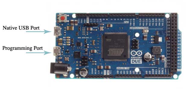
The Programming port is connected to an ATmega16U2, which provides a virtual COM port to software on a connected computer (To recognize the device, Windows machines will need a .inf file, but OSX and Linux machines will recognize the board as a COM port automatically). The 16U2 is also connected to the SAM3X hardware UART. Serial on pins RX0 and TX0 provides Serial-to-USB communication for programming the board through the ATmega16U2 microcontroller. The Arduino software includes a serial monitor which allows simple textual data to be sent to and from the board. The RX and TX LEDs on the board will flash when data is being transmitted via the ATmega16U2 chip and USB connection to the computer (but not for serial communication on pins 0 and 1).
The Native USB port is connected to the SAM3X. It allows for serial (CDC) communication over USB. This provides a serial connection to the Serial Monitor or other applications on your computer. It also enables the Due to emulate a USB mouse or keyboard to an attached computer. To use these features, see the Mouse and Keyboard library reference pages.
The Native USB port can also act as a USB host for connected peripherals such as mice, keyboards, and smartphones. To use these features, see the USBHost reference pages.
The SAM3X also supports TWI and SPI communication. The Arduino software includes a Wire library to simplify use of the TWI bus; see documentation for details. For SPI communication, use the SPI library.
Programming
The Due can be programmed with the Arduino Arduino Software (IDE). For details, see thereference and tutorials.
Uploading sketches to the SAM3X is different than the AVR microcontrollers found in other Arduino boards because the flash memory needs to be erased before being re-programmed. Upload to the chip is managed by ROM on the SAM3X, which is run only when the chip's flash memory is empty.
Either of the USB ports can be used for programming the board, though it is recommended to use the Programming port due to the way the erasing of the chip is handled :
- Programming port: To use this port, select "Arduino Due (ProgrammingPort)" as your board in the Arduino IDE. Connect the Due's programming port (the one closest to the DC power jack) to your computer. The programming port uses the 16U2 as a USB-to-serial chip connected to the first UART of the SAM3X (RX0 and TX0). The 16U2 has two pins connected to the Reset and Erase pins of the SAM3X. Opening and closing the Programming port connected at 1200bps triggers a “hard erase” procedure of the SAM3X chip, activating the Erase and Reset pins on the SAM3X before communicating with the UART. This is the recommended port for programming the Due. It is more reliable than the "soft erase" that occurs on the Native port, and it should work even if the main MCU has crashed.
- Native port: To use this port, select "Arduino Due (NativeUSBPort)" as your board in the Arduino IDE. The Native USB port is connected directly to the SAM3X. Connect the Due's Native USB port (the one closest to the reset button) to your computer. Opening and closing the Native port at 1200bps triggers a 'soft erase' procedure: the flash memory is erased and the board is restarted with the bootloader. If the MCU crashed for some reason it is likely that the soft erase procedure won't work as this procedure happens entirely in software on the SAM3X. Opening and closing the native port at a different baudrate will not reset the SAM3X.
More
This page is a shortened version of Arduino's official Due product listing. More info and the official listing can be found here. To set up your computer with the Due or for more setup information go here.