Basics of I2C - 180D-FW-2023/Knowledge-Base-Wiki GitHub Wiki
What is I2C?
I2C is a synchronous serial bus communication protocol which means it defines a specific way in which devices are allowed to communicate with each other. In I2C there are two types of devices: controller (previously referred to as master) and target (previously referred to as slave). The controller is the device that initiates communication and the target is a device that responds to the instruction from the controller. I2C is a protocol that can have multiple controllers and/or multiple targets. Typical usage of this protocol is for the controller to be a microcontroller and for the target to be a sensor, display, or memory chip. In this case, for instance, the microcontroller may want to get sensor data such as accelerometer readings, and the way it obtains these is by communicating using I2C.
Reference: https://learn.sparkfun.com/tutorials/i2c/all
As seen in the image above, I2C is a two wire protocol, meaning that there are only two physical wires necessary to transmit data. These two lines are SDA (Serial Data) and SCL (Serial Clock), both of which are bidirectional, meaning either the controller or target can write to them. The SDA line transmits the data and the SCL line carries the clock signal.
Since there is only one data line (SDA), the bits are transmitted serially–one after the other as opposed to in parallel–as the name implies. These bits are synchronized by the clock line (SCL) that all devices share hence why it is a synchronous protocol.
Advantages of I2C
I2C is a fairly cheap protocol to implement in applications in regard to how many pins and wires is necessary for it to be fully functional. It will only ever need two pins for each device for the aforementioned SDA and SCL, regardless of how many controllers and targets are on the bus. Additionally, it is not limited to a single controller and/or target so it is easily expandable.
Hardware of I2C
Each wire, SDA and SCL, is able to either be at a logic level of HIGH, which represents a 1, or at a logic level of LOW, which represents a 0. The voltages that indicate HIGH and LOW are determined by the devices’ specifications.
In order for SDA and SCL to be bidirectional, the I2C devices on the bus are open-drain/open-collector. This means that the devices are able to pull down the lines to a logic level of LOW, and they are unable to pull the line HIGH. Therefore, at any given point, the lines cannot be driven at two different voltage levels since devices only have the ability to drive the lines LOW.
Both SDA and SCL have a pullup resistor attached to it. If a device wants the line to go HIGH, it releases the line so the pullup resistor pulls it up to the voltage of the power rail which is the logic level of HIGH. This puts the line in a known state of HIGH rather than allowing the line to float (be at an unknown logic level). Thus, when no device is asserting it, the idle state of each of the lines is HIGH. The resistor is necessary so that the voltage rail is not shorted to a LOW voltage when a device drives the line LOW. The image below shows a typical setup where SDA and SCL are pulled up to VDD with a resistor with one controller and two peripherals.
Reference: https://www.analog.com/en/technical-articles/i2c-primer-what-is-i2c-part-1.html
When there are multiple controllers attempting to control the bus at the same time, only one can have control of the bus at a given point. At some point one of the controllers will release their assertion of LOW, expecting the line to be pulled up to HIGH, and if it is not, this means another device is controlling the bus. The controller that tried to let it go HIGH will stop its communication and release control, allowing the other device on the bus that is driving the line LOW to have control. This is what allows I2C to be able to have multiple controllers.
How I2C Transactions Work
This section focuses on the technical details of the communication that occurs across the I2C bus since these details are how I2C is able to have such a low pin count using only SDA and SCL.
Human Conversation Analogy
In general, when one person communicates with another person, the first person is either speaking a message to the second person or the first person is listening to a message that the other person is saying. This same logic applies to I2C. The controller—which is the one who initiates communication—either wants to write data to the target (speaking) or the controller wants to read data from the target (listening). In I2C, these communication actions are defined as transactions. A transaction is a full piece of communication between the controller and the target. Transactions are either a write or read operation.
The way these conversations typically begin and end is with a “hello” and a “goodbye”. Similarly, I2C has start and stop conditions which indicate the beginning and end of a transaction, respectively.
Messages communicated between people are made of words. In I2C there is a similar hierarchy where transactions are made up of frames. Frames are one byte and there are two types: address frames and data frames.
Address frames are similar to when someone starts a message off by saying the other person’s name to ensure the other person knows they are being spoken to. Each target that can be communicated with by the controller has a unique 7 bit address. Address frames contain the 7 bits of the target’s address and a read/write bit indicating the type of operation.
After one has been addressed, or their name spoken, is when the actual message begins to get communicated. This actual message is what the data frames are for. Data frames are 8 bits of actual data that needs to be communicated.
In human conversation, typically the person who is not speaking the message will every so often nod their head or murmur a “yes” to say they are understanding the message or they will say something like “no I did not understand” to convey the information was not understood. In I2C this idea exists in acknowledgements (ACKS) and no acknowledgments (NACKS). After every frame, the device that is reading the frame will send an ACK or NACK back across the line to give feedback.
Putting all the pieces of the human conversation analogy together, an I2C transaction is made up of a start and stop condition, an address frame, data frames, and acknowledgements (acks) and no acknowledgements (nacks). All of these are sent over SDA while being synchronized with SCL which the controller drives. The image below shows a whole transaction and the exact technical detail of these sections will be explained below.
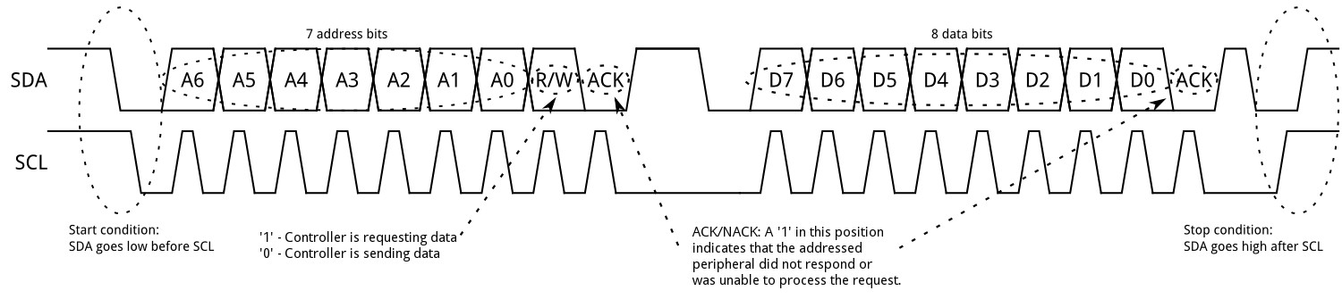
Source: https://learn.sparkfun.com/tutorials/i2c/all
Start and Stop Conditions
Start and stop conditions are the only times when SDA is allowed to change while SCL is HIGH. If SDA changes while SCL is HIGH during a transaction, it will be misinterpreted. In all other circumstances, SDA changes while SCL is LOW.
Start Condition
The start condition occurs at the beginning of a transaction and is initiated by the controller. This is what alerts the targets that a transaction is about to occur and they need to wake. A start condition is defined as when the SDA line goes from HIGH to LOW (pulled down by the controller) when SCL is HIGH.
In the case that there are two controllers trying to gain control over the bus, the one who pulls SDA down first wins. The other controller will see that SDA is LOW and know that another device is using the bus and will stop its transaction, waiting until the bus is free.
Stop Condition
The stop condition indicates the end of the transaction and is also generated by the controller. This tells the targets to go back to an idle slave. A stop condition is defined as when the SDA line goes from LOW to HIGH (by the controller) while SCL is HIGH.
Repeated Start Condition
A repeated start condition occurs during a transaction after the start condition but before the stop condition. It looks exactly like a start condition. It is used when the controller wants to do back to back transactions and does not want to release the bus for other controllers to potentially take over. It replaces a stop condition to an immediate start condition.
Address Frame
Address
I2C uses 7 bits to address the targets (0 to 0x7F) which gives 128 possible addresses for the targets as they must have unique addresses in order to be differentiated on the bus in communication, giving I2C the ability to have multiple targets on its bus. However, in practice there are some reserved addresses so there are less than 128 possible addresses for targets. The address comes immediately after the start condition, and it serially transfers the address bits starting from the most significant bit.
Read/Write Bit
After the last (7th) bit of the address is sent across, a bit that indicates if the transaction is a read or write operation is sent. Reading, which means the controller wants to read from the target, is indicated by a 1, and writing, which means the controller wants to write to the target, is indicated by a 0.
Data Frame
The data frame is 8 bits of data (1 byte) either sent by the controller or the receiver. They are sent with the Most Significant Bit first and contain the actual data of the transaction that needs to be communicated. Data frames are not sent until after the address frame.
ACK/NACK
After every frame, whichever device is receiving the data, must respond with either an acknowledgement (ACK) which is a 0 or a not acknowledgment (NACK) which is a 1. An ACK means that the byte was transmitted and received successfully whereas a NACK typically means that an error occurred. After a NACK, the devices can react appropriately such as ending the whole transaction or resending the data. One special circumstance of a NACK is that after the controller is finished reading from the target, it will send a NACK on its last byte to indicate it is done.
Example Transactions
In practice, many target devices have register files which is where they store their data and the controller will want to read or write from a specific register file. Therefore, the controller will need to first communicate which target device it wants to read from, then which register file on the device it wants to read or write, and then do the actual read or write operation. The following examples will operate under this structure.
Write Byte
The image below shows an example of a controller writing one byte to a register on a target. When the box is shaded this means the controller has control of SDA and when the box is white the target has control of SDA.
First there is a start condition and the controller sends this on the data line. Next is the address frame where there are 7 bits for the address of the target device and a 0 to indicate the controller wants to write to the target, again where the controller has control of SDA for this section. After this, the target takes control of SDA to acknowledge, letting the controller know it is ready and understood it was being addressed. Then the controller sends a data frame of the register address which the target acknowledges it received properly. The controller then sends another data frame, this time of the data to write to the register it communicated in the previous data frame, and the target acknowledges this as well. Finally, the controller sends the stop condition, indicating the transaction is over.
Read Byte
The image below shows an example of a controller reading one byte from a register on a target. Again, when the box is shaded this means the controller has control of SDA and when the box is white the target has control of SDA. This transaction is slightly different from the write transaction as the controller has to both write and read to the target in order to read a byte from a specified register on the target. This is because it needs to indicate to the target which register it wants to read from.
First there is a start condition and the controller sends this on the data line. Next is the address frame where there are 7 bits for the address of the target device and a 0 to indicate the controller wants to write to the target. After this, the target ACKs, letting the controller know it is ready and understood it was being addressed. Then the controller sends a data frame of the register address that it wants to read from which the target ACKs. Then the controller does a repeated start condition since now it wants to write rather than read from the target and so that it does not lose control of the bus to another controller. Now the controller again has to address the target, this time with a write bit, which the target has to ACK. Finally the target takes control of SDA to transmit the data that the controller wanted to read from the register the controller communicated earlier. Then the controller takes control of SDA again and will NACK this, indicating to the target that it is done with reading as it only wanted one byte. Finally, the controller sends a stop condition, finishing the transaction.
References
- https://www.circuitbasics.com/basics-of-the-i2c-communication-protocol/
- https://learn.sparkfun.com/tutorials/i2c/all
- https://www.analog.com/en/technical-articles/i2c-primer-what-is-i2c-part-1.html
- https://www.ti.com/lit/an/slva704/slva704.pdf?ts=1699159562162&ref_url=https%253A%252F%252Fwww.google.com%252F
- https://www.infineon.com/dgdl/Infineon-Component_I2C_V3.0-Software%20Module%20Datasheets-v03_05-EN.pdf?fileId=8ac78c8c7d0d8da4017d0e952b3f1fbe#:~:text=The%20I2C%20component%20is%20an,combination%20of%20masters%20and%20slaves.&text=This%20section%20describes%20the%20various,connections%20for%20the%20I2C%20component.
- https://www.allaboutcircuits.com/technical-articles/introduction-to-the-i2c-bus/