Basics of Modulation Schemes in Digital Communications - 115DAB/WS2024 GitHub Wiki
Basics of Modulation Schemes in Digital Communications
Group 9: Christopher Jayadi, David Feng

Fig. 1 Communications Graphic [1]
Introduction
Knowledge today is accessible from no further than the nearest device, but have you ever wondered how your devices manage to access information online so effortlessly? We often take this for granted but it’s incredible how we’ve engineered communications with the capability to transmit vast amounts of data across vast distances without any loss of information. A modulation scheme, or the method we use to organize data for transmission, is one key factor in our ability to transmit information.
Background on Bits and Symbols
Before diving into the various types of modulation schemes, it is important to first understand how data is stored on devices. Information is encoded in bits, with each bit’s value stored as a 0 or 1. The more bits sent, the more information available. In communications, m bits are typically organized into 2m symbols, with each symbol represented by a waveform. In an ideal world, sending information is errorless and instantaneous, but in reality, signal interference comes into play and messes with the electromagnetic waves that carry the information over time. This is where the need for modulation schemes comes in. By assigning a symbol to different waveforms, we can increase bitrate by a factor of “m” to send more information without increasing the frequency of the waveforms, which can be costly and is often subject to regulation [2].
Overview of Various Modulation Schemes
When designing waveforms for modulation schemes, a carrier wave is modulated to encode information. The carrier wave is typically set at a high frequency for a high symbol rate and combined with a message waveform for information; this message waveform is the target of a modulation scheme. The three main ways to encode information into the message waveform are through modifying amplitude, phase, and frequency, with representations in the time domain similar to Figure 2.
Fig. 2 Differences between Phase, Frequency, and Amplitude Shift Keying in Time Domain [3]
The most basic digital modulation schemes are called Amplitude Shift Keying (ASK), Phase Shift Keying (PSK), and Frequency Shift Keying (FSK), where shift keying refers to the switching between symbol keys. These modulation schemes can also be plotted into a constellation diagram for visualization, in which M symbols are represented as M points on an IQ plot where I represents the in-phase and Q represents the quadrature, or orthogonal, portions of the signal [2]. Distance to the origin is amplitude, angle to each point φ represents the phase/frequency, as seen in Figure 3. Symbol/bit error probability increases as interpoint distance decreases.
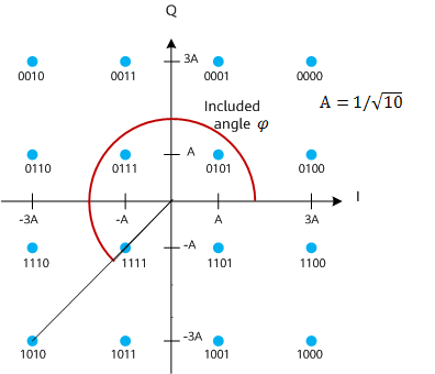
Fig. 3 Reading a Constellation Diagram [4]
Amplitude Shift Keying
In amplitude shift keying (ASK), the amplitude of the message waveform is modified to carry information with a symbol assigned to each waveform. To represent binary signals, a digital “1” can be represented as maximum amplitude, while “0” can be represented as minimum amplitude. This can be implemented by turning the signal on and off like morse code, known as on-off keying, with the disadvantage of putting stress on the systems and inducing noise in the signal. Typically, a continuous signal is modulated in amplitude to mimic this effect, known as modulation, which can be seen in Figure 4.
Fig. 4 ASK Signal in Time Domain [5]
This effect can be replicated to more than two levels of amplitude for M symbols, (M-ASK), however this is less common due to accuracy due to noise. ASK modulation has the advantage of being very simple and therefore cost-effective to implement. This comes at the cost of noise sensitivity and inefficiencies with power, making it more suitable for short range and imprecise communications. An alternative form of amplitude modulation is pulse width modulation (PWM) and pulse position modulation (PPM), which pulses the signal amplitude at various points in the signal period. Looking at Figure 5, although perfectly fine for low bandwidth data transmission, scaling the system up runs into issues with symbol error and energy, making the system suitable for low-power and limited applications requiring basic but accurate communications in relatively short ranges.
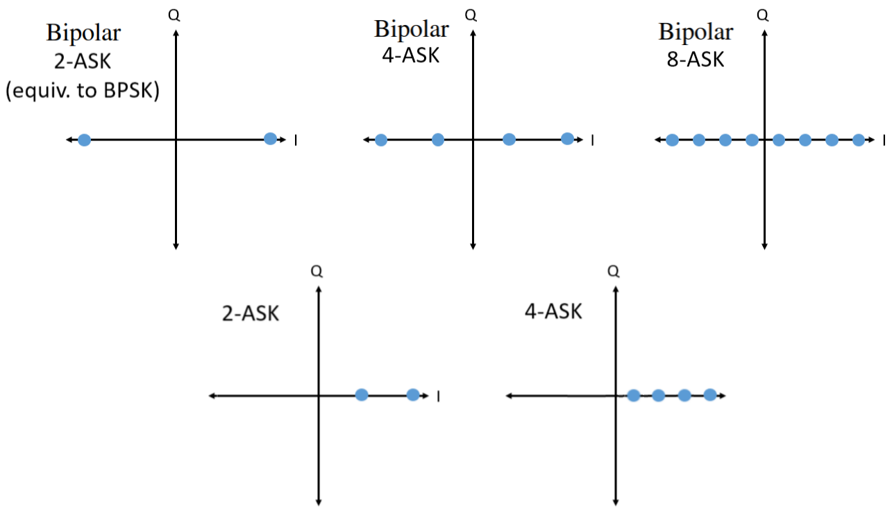
Fig. 5 Examples of ASK Constellation Diagrams [6]
Phase Shift Keying
For Phase Shift Keying (PSK), specific phases of the message waveform are assigned a symbol. These M symbols are typically distributed evenly through 360 degrees and can be represented by an M-PSK constellation. Using phase to carry information as seen in Figure 6 has the advantage of not relying as heavily on signal strength, unlike an M-ASK modulation scheme that depends entirely on signal strength.
Fig. 6 PSK Signal in Time Domain [5]
Instead, PSK modulation has the disadvantage of phase delay error where significant phase changes caused by the signal environment can result in significant errors in the received bits [2]. This is further exacerbated as the number of symbols increases, reducing the margin of error in phase and subsequently increasing error probability as in Figure 7. One way to correct for this is to use phase information of the carrier wave, but even then, differing frequencies may result in different phase delays.
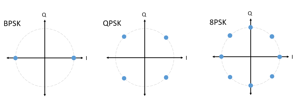
Fig. 7 Examples of PSK Constellation Diagram [6]
Compared to ASK modulation, PSK has a better error rate as the number of symbols goes up for a similar level of system complexity, but phase changes are much more unpredictable making PSK more suitable for longer distances or high-speed but low-accuracy applications with significant error checking capabilities.
Quadrature Amplitude Modulation
As the number of bits per symbol increases, the number of symbols necessary increases exponentially. As a result, using M-ASK or M-PSK modulation schemes alone will cause energy usage to also climb exponentially to maintain the same accuracy. One potential solution is to combine the two using Quadrature Amplitude Modulation (QAM), in which two orthogonal waveforms with varying amplitudes are combined to key in different symbols as in Figure 8.
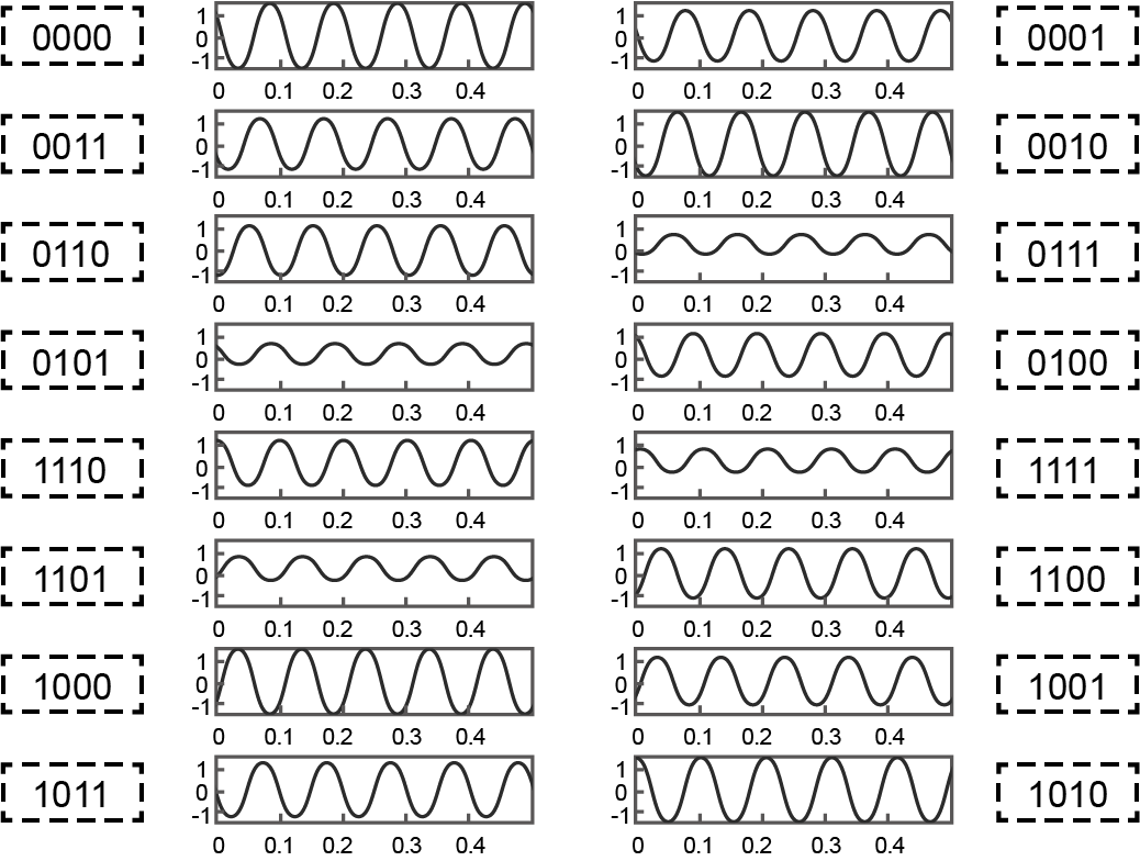
Fig 8. QAM Signal in Time Domain [4]
In this configuration, the constellation’s points are arranged in a square grid, maximizing the dimensions of data with minimum interpoint distances as in Figure 9. This results in a lower error rate at the same energy per bit compared to ASK or PSK alone, at the cost of device complexity and costs practically doubling. Combining the pros and cons of ASK and PSK, QAM is suitable for situations where relatively low energy but high data rates are necessary, device complexity and costs aren’t a big issue, and a good amount of error checking is available, like Wi-Fi routers limited by heat generation. For instance, Wi-Fi 5 utilizes the 256-QAM modulation seen in Figure 9.
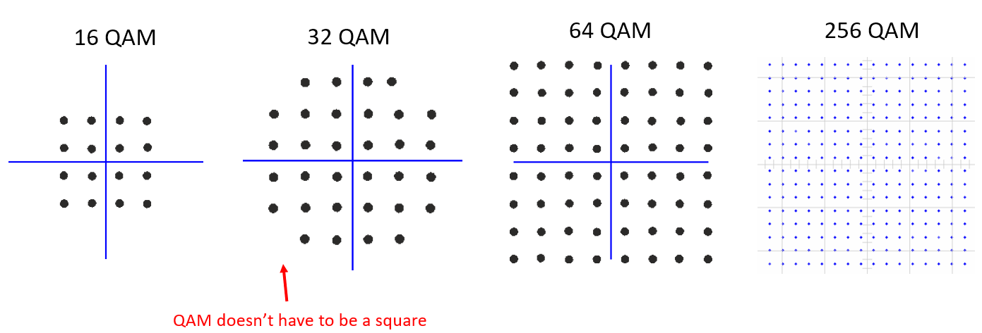
Fig 9. Example of QAM Constellation Diagram [6]
Similar to QAM is Amplitude-Phase Shift-Keying (APSK), with a difference in how the constellation is arranged. Rather than symbols being arranged in a square grid, symbols are arranged in a polar grid that can situationally reduce energy consumption and device complexity, with an additional disadvantage of poorer scaling capabilities like PSK, as seen in Figure 10.
Fig 10. Example of APSK Constellation Diagram [3]
Frequency Shift Keying
An alternative to using ASK, PSK, or a combination of these modulation techniques is Frequency Shift Keying (FSK), which assigns symbols to frequency offsets relative to a carrier signal’s frequency like in Figure 11.
Fig. 11 FSK Signal in Time Domain [5]
This has the advantage of complete signal orthogonality for improved accuracy equivalent to having an additional dimension in a constellation diagram for every signal, provided that the frequency shifting is accurate and far apart enough for signals to not overlap in the frequency domain due to noise. In addition, amplitude and phase are irrelevant to receive information as long as the signal is strong enough to be read, reducing reliance on signal accuracy at range. On the other hand, compared to ASK or PSK, device complexity increases to accommodate for the frequency switching and the higher signal frequencies typically reduce the range of the signals as real signals decay proportional to frequency. On top of this, heavy governmental regulations on signal frequency limits modulation to narrow frequency ranges, increasing noise from other devices and further increasing hardware costs to reduce the effects of noise on narrower frequency offsets. This makes FSK suitable for applications needing high data rates and low error rates with little concern for costs on transmission end, such as in FM radio stations.
Metrics to Compare Modulation Schemes
When considering which modulation scheme is best suited for a device, it is important to have some objective measures for comparison. One critical parameter is the bitrate required for an application given the maximum frequency and bits per symbol that the processing hardware can handle. Minimizing bit error probability is also important for operation, tying into the energy consumption per bit transmitted and the spacing between symbols. Overall, the stronger the signal, the less likely noise will change a symbol, which translates to more power required. On top of this, more complex modulation schemes will require more complex hardware to handle the processing. When it comes to choosing the correct modulation scheme for an application, it boils down to tradeoffs between power consumption, error rates, transfer rates, and complexity, not to mention the strict regulations on wireless modes of communication.
Conclusion and Future Outlooks of Communication Systems
When looking at the overall implementation of a communications system, modulation schemes make up only a small portion of what makes communication possible. However, they are a fundamental component in the transmission of information based on three basic properties of a sinusoidal waveform, its amplitude, phase, and frequency. Each type of shift keying has its own advantages and disadvantages, such as trading bandwidth for signal strength on ASK, or increasing complexity to mitigate losses on FSK etc. Thus, each has its own set of applications in communications that utilize their unique strengths. There are many more considerations beyond modulation schemes necessary for communications, such as encoding extra bits for error detection, the channels used for communications, and even the circuitry used to actualize the modulation scheme itself. Despite being a small fraction of the entire system, modulation schemes are essential for information to be received accurately at a low cost in a timely manner, as seen in Figure 12 and [7]. The possibilities for new and improved modulation schemes are limitless and give us access to exponentially increasing data transfer rates such as 9.6 Gbps speeds through Wi-Fi 6’s 1024-QAM scheme, 46.1 Gbps speeds through Wi-Fi 7’s 4096-QAM scheme, and even faster speeds in the upcoming generations using even more sophisticated modulation schemes combining FSK modulation as described in [8].
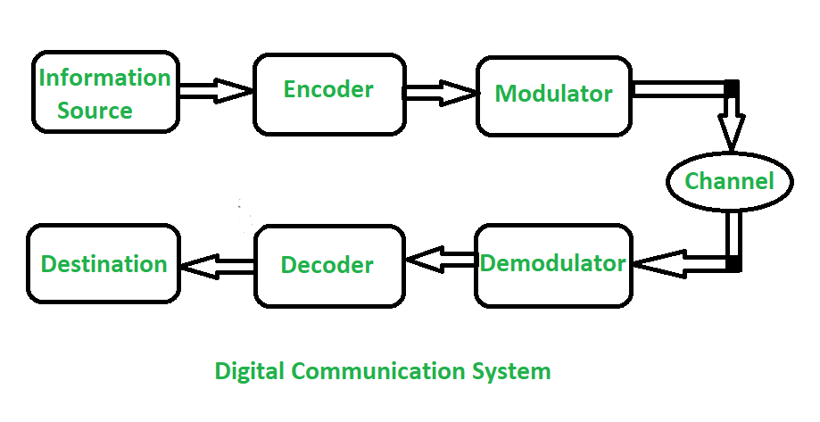
Fig. 12 Digital Communications System Diagram [6]
References
[1] N. Apadula, “Advance Your Skills in Wireless Communication Technologies,” IEEE.org, [Online]. Available: https://spectrum.ieee.org/wireless-communication-technologies-courses
[2] “Application Note AN-005: Understanding Constellation Diagrams and How They Are Used,” NuWaves Engineering, [Online]. Available: https://nuwaves.com/wp-content/uploads/AN-005-Constellation-Diagrams-and-How-They-Are-Used1.pdf
[3] CadenceSystems, “Types of Digital Modulation.” Cadence Resources, [Online]. Available: https://resources.system-analysis.cadence.com/blog/msa2021-types-of-digital-modulation
[4] Z. Xia, “What is QAM?,” Huawei, [Online]. Available: https://info.support.huawei.com/info-finder/encyclopedia/en/QAM.html
[5] S. Faruque, “Free Space Laser Communication with Ambient Light Compensation,” SpringerNature, [Online]. Available: https://link.springer.com/chapter/10.1007/978-3-030-57484-0_9
[6] M. Lichtman, “A guide to SDR and DSP using python,” PySDR, [Online]. Available: https://pysdr.org/content/digital_modulation.html
[7] S. Jena, “Difference between Analog and Digital Communication,” GeeksForGeeks, [Online]. Available: https://www.geeksforgeeks.org/difference-between-analog-communication-and-digital-communication/.
[8] TP-Link Editorial Group, “WiFi 7 vs WiFi 6: How is WiFi 7 Different From WiFi 6?” TP-Link, [Online]. Available: https://www.tp-link.com/us/blog/730/how-is-wifi-7-different-from-wifi-6-/