Basics of Linear Voltage Regulators - 115DAB/WS2024 GitHub Wiki
Group 3: Zayyir Ahmed, Arthur Yang, Thomas Chu
Introduction & Background
In many modern electronics systems, the complexity resulting from increased power supply demands by loads, such as up to 100A for ASIC systems, requires power management design solutions [2]. Linear voltage regulation is one way to maintain load voltage and current requirements in a given system. Linear voltage regulators are systems involving pass transistor elements and closed feedback loops configured in various topologies that can act to ensure a steady output voltage lower than the input voltage, across a given output load irrespective of input voltage fluctuations [7].
Linear voltage regulators offer several advantages in simplicity in implementation, low noise and RF radiation, and speedy response for load voltage regulation, despite their disadvantages in low energy through heat dissipation [6]. Thus, critical factors impacting linear voltage regulator design and use involve input voltage range, a required output load voltage, output load current, and optimized power dissipation. Overall, linear voltage regulators are vital for ensuring the stability and correct functioning of modern electronic systems in the face of voltage fluctuations across a wide range of applications, particularly in electronic devices and systems involving power supply regulation and communications applications.
How Linear Regulators Work
One example of a simple linear regulator can be implemented via a single zener diode, as shown below [11]:

The output voltage is regulated to the zener diode’s reverse breakdown voltage. In reverse breakdown mode, the zener diode has an extremely steep I-V curve. Any increase in VS will result in an increasing current through the diode instead of an increasing current through RL. However, VS * (RL)/(RL + RS) cannot be less than the desired output voltage.
The following figure [1] shows the schematic for a feedback-based linear regulator. Assuming infinite gain, the OPAMP’s feedback ensures that the voltage at VOUT is always equal to VREF * (1 + R1/R2). The remainder of the voltage, VIN - VOUT, is dropped across the output driver transistor.
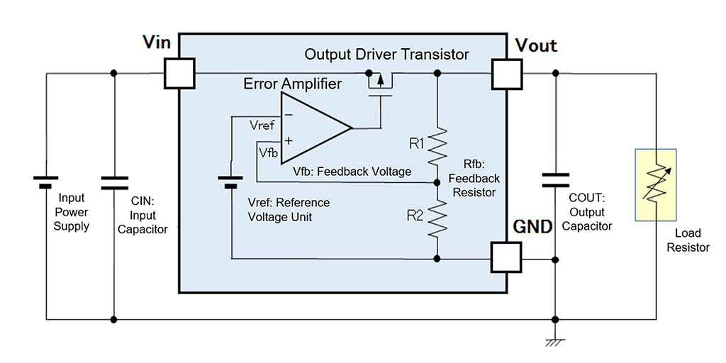
The linear regulator allows VOUT to maintain a constant voltage regardless of the characteristics of the load. If The load resistance decreases, VOUT decreases, which causes the gate voltage of the driving PMOS to decrease, thus increasing the current through the load again. The same effect happens in reverse when the load resistor increases.
Capacitors are inserted at the input and output of the linear regulator to reduce sudden changes in voltage.
The use of feedback in linear regulators introduces the possibility of instability. At certain frequencies, phase shifts caused by poles may exceed 180 degrees. If the gain is greater than 1 at those frequencies, positive feedback will occur. Thus, if the linear regulator is not carefully designed, oscillations may occur at the output.
The output capacitor and load must be chosen to ensure stability. The exact location of the poles depends on the linear regulator and its loads’ components.
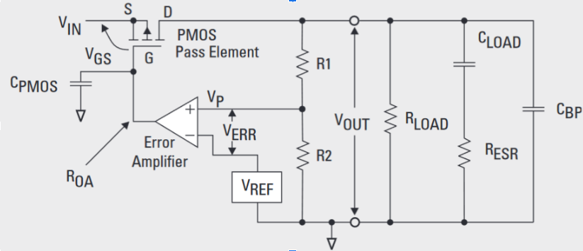
In the above graph [5], CLOAD and RLOAD cannot be too low, or else the system will become unstable. Users must complete a full analysis using the system’s open-loop transfer function.
One particular kind of linear voltage regulator is a low-dropout (LDO) regulator. The concept of LDOs is to minimize the input-to-output voltage across the regulator to enhance energy efficiency, with the minimum input-to-output voltage difference termed as “dropout voltage” [9].
Applications of Linear Voltage Regulators
Linear regulators can only provide step-down DC-to-DC conversion, thus finding themselves used extensively to power circuit blocks that require a smaller voltage than the given supply. For example, consider a scenario where a design requires motors, sensors, and microprocessors - it would be nonsensical to generate separate supplies for 9 V, 5 V, or 3.3V - when linear regulators can be used to convert a base 9V to whatever voltage is needed for proper operation, lowering cost and space. linear regulators find themselves most extensively used in communications, data converters, portable devices & instruments, industrial/automotive applications, and digital logic core supply (MCUs, I/Os, PHY, CPUs, GPUs, and RAM are some examples) [3].
For communication systems (both wired and wireless) that contain very sensitive analog circuits where noise and response time are critical, low-noise and high power supply rejection ratio (PSRR) linear regulators are desired. For equipment that needs to be mobile and cost-effective (especially with the increase of IoT devices) small form-factor, low-power linear regulators are growing in demand. With the rise of automation in industrial sectors, alongside the increase in electric cars in the automotive industry, the need to handle larger voltages is a necessity, hinting towards high-voltage operation linear regulators [3].
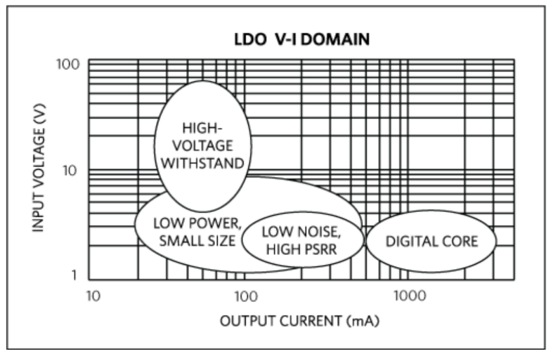
Fig. Input Voltage vs Output Current of a general linear regulator [3]
Limitations
Depending on the application, linear regulators are designed with specific performance metrics in mind, with less important parameters neglected in the trade-off. However, generally speaking, there are still non-idealities that plague the linear regulator and limit its performance - some of which are linear regulator specific and some which are a byproduct of IC design. These include cost, size, DC offset, power loss, transient settling time, high-voltage, stability, PSRR, reverse-current protection, short-circuit and thermal overload protection, and more. Many of these parameters are intertwined - size, power loss, high-voltage, and thermal overload often overlap and of course, cost tends to be sought after regardless if you are making a linear regulator or using a linear regulator in a system [3, 5, 7].
Linear regulators often need a certain amount of headroom to operate - for a large step-down we ensure that there is necessary headroom but then our efficiency is poor. Low Dropout regulators (LDOs) are a type of linear regulator that is meant for relatively small differences between the desired output voltage and a given input voltage - the larger this voltage differential is the worse the efficiency of the linear regulator. As the voltage differential increases, we also see a degradation in our maximum supplied current at the output, potentially limiting our output power. This means that if your design must make large jumps while stepping down, it would potentially be better to use a switch-mode power supply, which typically has higher efficiency for large jumps compared to linear regulators then cascade a linear regulator after. This way, you still get the benefits of a linear regulator over an SMPS (less noise and ripple at the output), while not needing as much heat dissipation in the form of a heat sink (which takes up space & cost) for the large step-down. In fact, many linear regulators are designed for use in a cascade, where they can lower the output voltage of the previous converter using a feedback pin (called VIOC for the LT3073) to raise their efficiency, as shown in the LT3073 which came out last year by Analog Devices [8]. Another limitation is output drive capability, for applications that require a larger current it is common to place several linear regulators in parallel to boost the current drive. This of course has its own tradeoffs associated with performance, cost, size, and heat dissipation but does alleviate some of the potential pitfalls of linear regulators.
Current Research & Future Developments
As discussed previously, linear voltage regulators tend to suffer from the challenge of high power dissipation. Some of the ongoing research and developments in linear regulators are thus focused on addressing this issue. One of the approaches is combining switching regulators, which offer the benefits of lower power dissipation while retaining the low-noise and RF radiation advantages of linear regulators. For example, Vasić et al. [9] have studied theoretical optimization methods for parallel and series configurations of linear-assisted switching converters for envelope amplifiers used in communication systems. In their research, it was found that the configuration of switching converters in series with linear regulators has approximately 10% higher efficiency compared to parallel linear-assisted switching converters. Furthermore, Liu et al. [10] have developed envelope amplifiers for based on such a series of linear-assisted switching converters. Their design divides the linear regulator into a current amplifier stage, driving stage, voltage amplification stage, and feedback stage, which achieves a maximum of 40 V output and up to 5 MHz bandwidth of high tracking capability.
Summary
Linear regulators are used to supply a steady output voltage out of a higher supply voltage. They can smooth out supply disturbances or power components that require a lower voltage. However, the difference in voltage between the supply and output is dissipated as heat. This makes linear regulators inefficient as the output voltage is small compared to the supply voltage. Switching regulators should be considered in these cases.
References
[1] “What is a linear regulator (LDO regulator)?,” Design Supports | Nisshinbo Micro Devices, https://www.nisshinbo-microdevices.co.jp/en/design-support/basic/02-linear-regulator.html (accessed Feb. 18, 2024).
[2] H. Zhang, “An-140: Basic concepts of linear regulator and switching mode power supplies,” Basic Concepts of Linear Regulator and Switching Mode Power Supplies | Analog Devices, https://www.analog.com/en/resources/app-notes/an-140.html (accessed Feb. 18, 2024).
[3] “Low-dropout linear regulator (LDO) Application Tutorial,” Analog Devices, https://www.analog.com/en/resources/technical-articles/lowdropout-linear-regulator-ldo-application-tutorial.html (accessed Feb. 18, 2024).
[4] “Linear Voltage Regulator: How It Works, Application & Advantages,” Electricity - Magnetism, https://www.electricity-magnetism.org/linear-voltage-regulator/ (accessed Feb. 18, 2024).
[5] E. Rogers, “Stability analysis of low-dropout linear regulators with a PMOS pass element,” Texas Instruments, https://www.ti.com/lit/an/slyt194/slyt194.pdf?ts=1708028706088 (accessed Feb. 19, 2024).
[6] J. Williams, “High Efficiency Linear Regulators,” Analog Devices, https://www.analog.com/media/en/technical-documentation/application-notes/an32f.pdf (accessed Feb. 19, 2024).
[7] D. Knight, “Introduction to linear voltage regulators,” Digikey, https://www.digikey.com/en/maker/tutorials/2016/introduction-to-linear-voltage-regulators (accessed Feb. 19, 2024).
[8] Analog Devices, “3A, Ultra-Low Noise, High PSRR, 45mV Dropout Ultra-Fast Linear Regulator”, LT3073 datasheet, January 2023, https://www.analog.com/media/en/technical-documentation/data-sheets/lt3073.pdf (accessed Feb. 19, 2024)
[9] M. Vasić, O. García, J. A. Oliver, P. Alou and J. A. Cobos, "Theoretical Efficiency Limits of a Serial and Parallel Linear-Assisted Switching Converter as an Envelope Amplifier," IEEE Transactions on Power Electronics, vol. 29, no. 2, pp. 719-728, Feb. 2014, doi: 10.1109/TPEL.2013.2257855 (accessed Feb. 19, 2024)
[10] M. Liu, D. Zhang and Z. Zhou, "Linear Regulator Design Considerations of the Serial Linear-Assisted Switching Converter Used as Envelope Amplifier," IEEE Transactions on Power Electronics, vol. 31, no. 5, pp. 3673-3689, May 2016, doi: 10.1109/TPEL.2015.2463122 (accessed Feb. 19, 2024)
[11] “The Zener Diode,” Last Minute Engineers, https://lastminuteengineers.com/the-zener-diode/ (accessed Feb. 18, 2024).