Software Architecture and Design - 1024mb-Wits/moodle_plugin GitHub Wiki
This page describes the software architecture and design according to our current system and current client requirements.
High-level overview of the system and high-level sections of the system
Our software architecture style is a multi-tier style with 3 tiers. These 3 tiers are:
-
The presentation tier: This tier handles the user interface. It is displayed on the client's browser. This would include our HTML tree widget (which uses CSS for styling).
-
The application/logic tier: This tier handles the logic of the system. It includes middle-layer software such as Node.js (which we will be using) that processes content and handles client requests. This tier includes the JavaScript files that will be used to integrate our tree widget into Moodle.
-
The database tier: This tier handles the storage and retrieval of the data and involves the back-end database and database management system. In our system, we use a MySQL database and PHP to store and retrieve data. The data we are storing includes question settings, model answers to assessment questions, student answers, strings defining the structure of trees built and more.
The diagrams below describe a high-level overview of our software architecture.
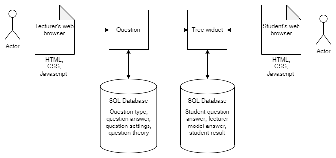
These diagrams depict the users, lecturers and students, and how they interact with the front end (which uses HTML, CSS and JavaScript to be displayed correctly) and the SQL databases in the back end. For lecturers, when creating a question the database provides information about question types and stores information about the settings of the question. When students interact with the question provided by the lecturer, they use the tree widget. Their answer will be stored in the SQL database, as will their result when it has been produced by the automatic marking within the plugin.
Architectural Viewpoints
4 + 1 Architectural View Model
Below we describe our system architecture in terms of the viewpoints that comprise the 4+1 Architecture View model.
Logical View
The logical view supports the functionality (or services) that the system should provide to its users. It includes the decomposition of the system into key abstractions in the form of objects and classes, which make use of inheritance and encapsulation.
The actors in our system include lecturers, students, and the Moodle plugin. The Moodle plugin involves the use of the HTML widget for tree construction and editing, as well as question types. Our system also includes a renderer, which will be used to process and display trees in Moodle.
The decomposition of our software system into classes and objects is as follows:
| Classes | Class description |
|---|---|
| Tree widget | The tree widget itself provides functions that allow the users to construct and edit AVL trees. |
| Question type AVL | This will be a question subtype for the direct use of creating questions based on AVL trees. |
| Renderer | The renderer will be used to interpret or process the tree widget and any information in them to display them correctly as well as obtain the information from student trees for marking. |
| Lecturer | The lecturer will be able to create instances of the question type AVL class to create questions for assessments. They will interact with the tree widget to construct trees for questions as well. |
| Student | The student will be able to use the tree widget to construct and edit AVL trees to answer questions created by the lecturer. |
in detail, our users, the lecturers and students, will have the following functionality provided to them:
Lecturer:
- The lecturer will be able to create a new question of type AVL.
- The lecturer will be able to alter the settings of the question they create; they will be able to choose what the question content is in terms of theory.
- The lecturer will be able to construct and edit an AVL tree using the HTML widget provided by the plugin. The actions they can perform include:
- adding nodes to the canvas
- adding edges between nodes on the canvas
- dragging nodes across the canvas
- deleting nodes and edges from the canvas
- editing the value of nodes on the canvas
- The lecturer will be able to add the question they have created to quizzes or assessments on Moodle.
In later sprints, the plugin will automatically mark any answers submitted by the student, though this functionality is not yet supported and is therefore not represented in our UML diagrams.
Student:
The student will be able to construct and edit trees by having the following actions available to them:
- adding nodes to the canvas
- adding edges between nodes on the canvas
- dragging nodes across the canvas
- deleting nodes and edges from the canvas
- editing the value of nodes on the canvas
- editing the height of a node
The state diagram below depicts how the objects of the system interact to provide this functionality to the users.

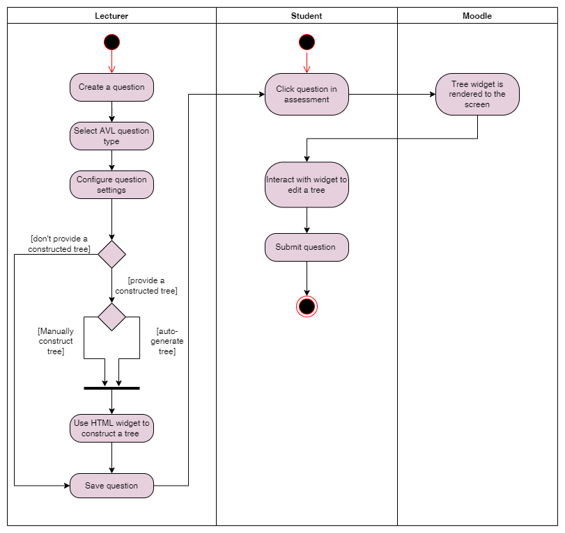
Process View
The process view focuses on the system processes and how they communicate. It takes into account some non-functional requirements, as it is concerned with how the system behaves when running. In our system, we are mainly concerned with the processes involving the users: we are essentially describing the processes that The following activity diagram depicts a process view of the system; it shows the processes of the system through activities performed by the system. Activity diagrams are behavioural diagrams.
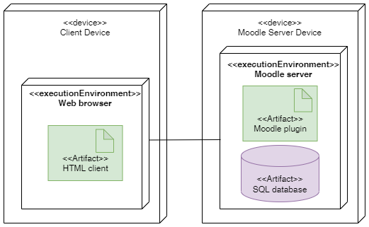
Physical View
The physical view is concerned with the physical aspects of the system: how it is physically distributed, how the distributed parts are physically connected, and how the software is mapped to the hardware. This relates to the system engineer’s point of view of the system.
The following deployment diagram, which is a structural diagram, depicts the physical view of our software system:
Scenarios or Use Case View
This view uses the use cases (the way that roles interact with the system to achieve goals) to describe the system architecture. Use case diagrams, which are behavioural diagrams, are used to represent the use case view. The use case diagram below depicts the goals of our users: for lecturers, that goal is to create a question for an assessment, and for students, that goal is to answer the question created. These goals are the base cases in our use case diagram. The diagram also depicts what use cases are included in those base cases; in other words, the use cases that are required for those base cases to be complete.

Development View
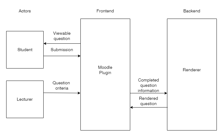
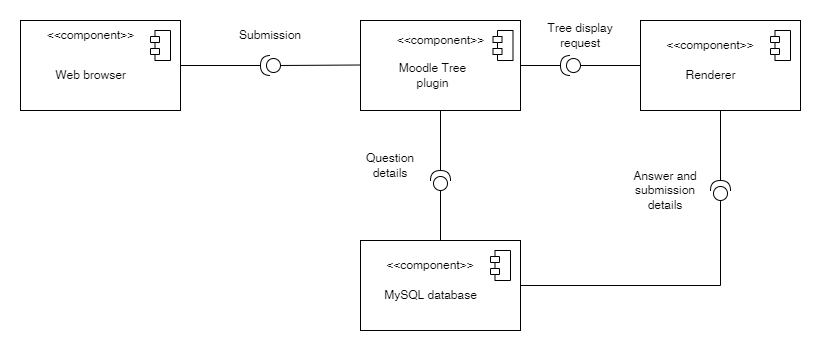
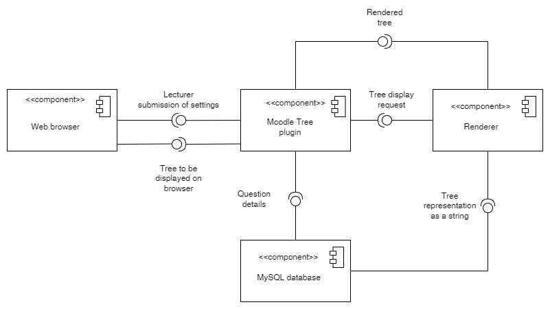
The development view of software architecture is concerned with how the software itself is organised from the point of view of the programmers. The software is decomposed into subsystems containing interfaces. This view describes the components of the software and how they interact.
Our system comprises the following components and interfaces:
- Web browser: requires the Moodle plugin, which will use the renderer to display items to the users (lecturers and students)
- Moodle Tree plugin: uses MySQL database for storage of information such as question types, question settings, model answers, student answers et cetera. The plugin requires this database to work; without it, it cannot process the necessary information for generating questions, and it cannot store tree information.
- Renderer: The renderer will be used to interpret or process the tree widget and any information in them to display them correctly as well as obtain the information from student trees for marking.|
- MySQL database: storage of information such as question types, question settings, model answers, student answers et cetera.
Component diagrams, which are structural diagrams, include components (modular aspects of the system), interfaces, and subsystems. The component diagrams below depict the decomposition of our software system into these components and interfaces.
Sprint 3:
Sprint 4:
Previous Sprints Software Architecture
If you wish to view diagrams from the sprints prior to the current sprint, you can find them on this project's Taiga page.