Honda Prelude 1993
See also Honda Accord 1995
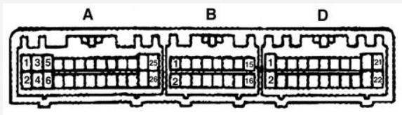
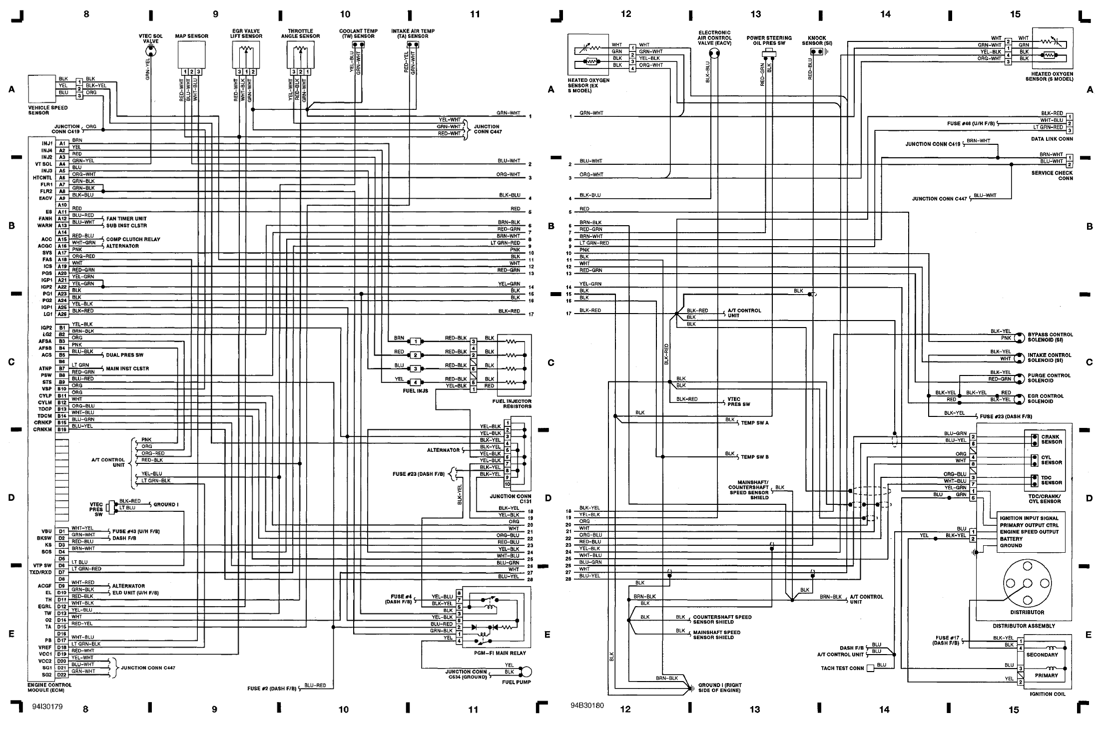
| A1 | W63 | BRowN | Injector #1 | Output |
| A2 | W64 | YEL | Injector #4 | Output |
| A3 | W61 | RED | Injector #2 | Output |
| A4 | W62 | * | * | * |
| A5 | W59 | BLUe | Injector #3 | Output |
| A7 | W57 | GRN/BLK | Fuel Pump Relay | Output, sink/low |
| A8 | W58 | * | * | * |
| A9 | W55 | BLK/BLU | Idle Air Control Valve | Output, sink/low. 500Hz |
| A12 | W54 | GReeN | Radiator Fan Control Module | Output |
| A13 | W51 | LTGRN/RED | MIL | Output, low-side |
| A22 | W44 | * | * | * |
| A23 | W41 | BLK | Power Ground | Ground |
| A24 | W42 | BLK | Power Ground | Ground |
| A25 | W39 | YEL/BLK | Power Source | Input, +12 if ignition is on |
| A26 | W40 | BRN/BLK | Logic Ground | Ground |
| B2 | W38 | BRN/BLK | Logic Ground | Ground |
| B10 | W30 | ORG | Vehicle Speed Sensor | Input (grounded 4 times per speedometer cable revolution) |
| B11 | W27 | ORanGe | CYP Signal | Input, one pulse per cam rev |
| B12 | W28 | WHT | CYP Ground | |
| B13 | CAM- | ORG BLU | TDC Signal | Input, four pulses per cam revolution |
| B14 | CAM+ | WHT BLU | TDC Ground | |
| B15 | CNK- | BLU GRN | CKP Signal | Input, 24 pulses per cam |
| B16 | CNK+ | BLU YEL | CKP Ground |
| D3 | W19 | * | * | * |
| D11 | W11 | RED/BLK | Throttle Position Sensor | Input |
| D13 | W9 | RED/WHT | Engine Coolant Temperature Sensor | Input |
| D15 | W7 | RED YEL | Intake Air Temperature Sensor | Input (bias pull-up 1.5K) |
| D16 | W8 | * | * | * |
| D17 | W5 | WHiTe/YELlow | MAP Sensor | Input: 0.32V @ -13.9 PSI, 4.84V @ 10.94 PSI |
| D20 | W4 | YEL BLU | VCC2 TPS, EGVL sensor power supply | Output +5V |
| D21 | W1 | GRN/WHT | SG1 MAP sensor GND | Ground |
| D22 | W2 | GRN BLU | SG2 - Sensors Ground | ground |