HOWTO Miata NB2 on Proteus
This page is still WIP
See also Mazda-Miata-2003
Disclaimer : This page has been written by a user and thus might not be objective
A plug and play adapter board has been developped to get the car to work as easy as possible. It only requires sourcing a tock harness plug and Ampseal 23 pins headers if you want auxiliary functions. More informations are available at this link :
Proteus Plug and Play board for Miata/MX5 NB2 (72 pins)
This board is meant to run an NB2 Miata on Proteus V0.3 or above ECU. IT saves you a lot of time on crimping a custom wiring harness to accomodate OEM connector, and is overall a cheaper alternative as well. Leds indicators let you see which outputs are activated, and included flyback diode let you run the big inductive loads without risk for the Proteus low side drivers.
All the OEM pins are wired through a bridge closed by either a 0 ohm 0805 jumper or a jumper wire, letting you reallocate OEM connector pin as you want.
Two 23 pins Ampseal extension connectors allows you to wire more functions like boost control, WBO2, CAN bus communication, ETB, etc.. You can use all outputs Proteus has to offer you and on a 4 cylinder with single VVT it means a lot of extra functions.
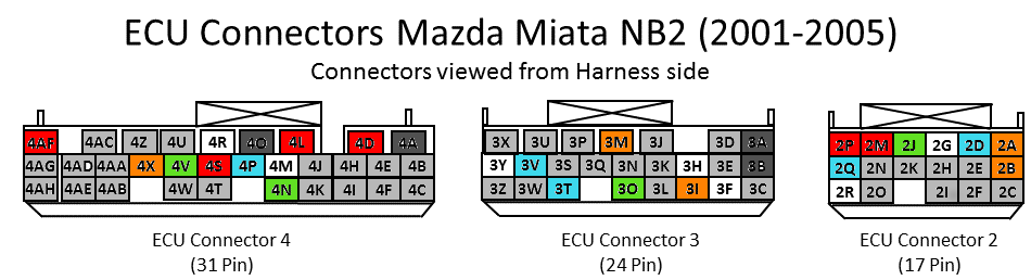
The board pin mapping for OEM connector follows the tab given in the Pinning section below.
For the extension connectors the pinnig is the following :
| PnP extension pin | Proteus pin | Type ID | Comment |
|---|---|---|---|
| 1A | B21 | Lowside 12 | |
| 1B | B10 | Lowside 13 | |
| 1C | B11 | Lowside 14 | |
| 1D | B12 | Lowside 15 | |
| 1E | B23 | Lowside 16 | |
| 1F | B34 | Ignition 2 | |
| 1G | B33 | Ignition 4 | |
| 1H | B32 | Ignition 5 | |
| 1I | B31 | Ignition 6 | |
| 1J | B30 | Ignition 7 | |
| 1K | B29 | Ignition 8 | |
| 1L | B28 | Ignition 9 | |
| 1M | B27 | Ignition 10 | |
| 1N | B26 | Ignition 11 | |
| 1O | B25 | Ignition 12 | |
| 1P | Ground | ||
| 1Q | Ground | ||
| 1R | Ground | ||
| 1S | Ground | ||
| 1T | High Side 2 | ||
| 1U | High Side 4 | ||
| 1V | A12 | 12V Protected 2 | |
| 1W | Ground | ||
| 2A | C17 | CAN+ | |
| 2B | C16 | CAN- | |
| 2C | VR1+ | ||
| 2D | VR1- | ||
| 2E | VR2+ | ||
| 2F | VR2- | ||
| 2G | Analog Temp 3 | ||
| 2H | Analog Temp 4 | ||
| 2I | Analog Volt 1 | Used for MAP input | |
| 2J | Analog Volt 2 | Used for WBO2 input | |
| 2K | Analog Volt 7 | ||
| 2L | Analog Volt 8 | ||
| 2M | Analog Volt 9 | ||
| 2N | Analog Volt 10 | ||
| 2O | Analog Volt 11 | ||
| 2P | Analog Volt 12 | ||
| 2Q | A21 | 5V Sensor 1 | Used for MAP sensor |
| 2R | A10 | 5V Sensor 2 | |
| 2S | Ground | Used for WBO sensor | |
| 2T | ETB1+ | ||
| 2U | ETB1- | ||
| 2V | ETB2+ | ||
| 2W | ETB2- |
At the moment, the interface between Proteus board and the PnP adapter is handled by hacked up Ampseal connectors. To do that you need to source the male connectors used on Proteus, and cut the plastic shroud on the connector side, flush with the watertight seal if there is any, or with the mounting flange.
A better solution for that would be to source rows of headers with the correct pitch.
Unit price for QTY 5 assembled and delivered to Europe is 7$.
A few improvment would make this board really plug and play and easier to use
- For now the MAF input doesn't work because it lacks some pullup/pulldown.
- Altough they fit in OEM ECU location, ampseal extension connectors are a bit bulky. They were chosen because board designed had them lying around.
| Pin Number | Name | Proteus pin | Type ID | Default function |
|---|---|---|---|---|
| 2A | Inj 1 | B3 | Low-Side 1 | Injector #1 |
| 2B | Fan | B9 | Low-Side 11 | Radiator Fan Control Relay Output |
| 2C | A/C Fan | -- | Low-Side xx | A/C Fan Control Relay Output |
| 2D | Inj 2 | B15 | Low-Side 2 | Injector #2 |
| 2G | Inj 3 | B4 | Low-Side 3 | Injector #3 |
| 2J | Inj 4 | B16 | Low-Side 4 | Injector #4 |
| 2O | - | x | x | |
| 2M | Fuel Pump | B6 | Low-Side 6 | Fuel Pump Relay Output |
| 2P | IAC Feed | 12V | Idle Valve Power | |
| 2Q | IAC Control | B7 | Low-Side 7 | Idle Valve Control |
| 2R | MIL | B20 | Low-Side 10 | Check Engine Light output |
| - | - | - | - | - |
| 3A | GND | A1 | Power Ground | Ground |
| 3B | GND | C19 | Power Ground | Ground |
| 3F | Coil #1 | B35 | Ignition 1 | Coil #1 control |
| 3I | Coil #2 | B22 | Ignition 3 | Coil #2 control |
| 3H | Main Relay | B5 | Low-Side 5 | Main Relay Control |
| 3K | - | x | x | |
| 3L | - | x | x | |
| 3M | Alternator | B1 | High-Side 2 | Alternator Control Output |
| 3N | - | x | x | |
| 3O | Tach | B2 | High-Side 1 | Tachometer Output |
| 3T | VSS | ? | ? | Vehicle Speed Sensor |
| 3V | Cam | C1 | Digital 2 | Cam shaft Hall Input |
| 3U | Alt Warn | x | x | |
| 3Y | Crank | C10 | Digital 1 | Crank shaft Hall Input |
| 3Z | - | x | x | |
| - | - | - | - | |
| 4A | GND | Ground | Ground | |
| 4D | VVT Feed | 12V | VVT Power | |
| 4K | - | |||
| 4L | - | A21 | 5v Sensor 1 | OEM 5V Sensor Power |
| 4N | IAT | A20 | Analog Temp 3 | Intake Air Temperature Sensor |
| 4O | GND | A23 | GND | Sensor Ground |
| 4P | CLT | A19 | Analog Temp 1 | Coolant Temperature Sensor Input |
| 4R | VVT | B8 | Low-side 9 | VVT Control |
| 4S | Key | C18 | 12V RAW | +12v from Ignition Key |
| 4V | TPS | A14 | Analog Volt 3 | Throttle Position Sensor |
| 4X | MAF | A25 | Analog Volt 4 | Mass airflow sensor, needs pulldown |
| 4AE | EGR Boost Sensor | A16 | Analog Volt 7 | MAP |
| 4AF | Main Relay Power | C23 | 12V MR | +12v from Main Relay |
Using an external MAP sensor allows you to get the engine running above ambiant pressure when using forced induction. Good cheap option is GM 3 bars but anything will work for you. MAP input can be mapped to Analog Volt 1 (A13 pin).
Note : You can also run the engine naturally aspirated using the OEM "boost sensor". It is located on the EGR systems and is used by stock ECU to determine whether the EGR is working or not. You've probably ditched EGR so far and so you can run a vacuum line from your plenum to this sensor and use it with this calibration:
- 0V - 15Kpa
- 5V - 115Kpa
Or you can use the OEM sensor for barometric reading and correction.
VVT is quite picky to tune on the miata
You can replace the OEM 4 tooth crank trigger plate located between timing belt pulley and accessory belt pulley with a Mazda Protege trigger wheel. It is bolt on, meaning you just have to remove damper pulley to get it in place (it has a good chance to be stuck depending on car condition) and you get a way better trigger resolution of 10 degrees for a very low cost. Trigger wheel from mazda dealership was 12€ in France, available quickly. Part number is #ZM 01-11-408. For european folks your dealer might think this is an invalid number, but if he enters it the part will be offered by Mazda Europe. This modification is also applicable t any other miata with same crank bolt pattern.
Tune-wise you will need to switch to "4 stroke without cam sensor" configuration and to set your timing correctly. My offset value, verified with a timing light is 76 degrees. You can probably start your car with it, but be extra careful and check your timing with a timing light afterwards.
The gain might not be felt by everyone, but on RE the cranking will be easier, and you will get a smoother running engine. Best of all, if your fuc**** cam sensor decides to die as it does quite often you can run your car without VVT in batch injection and wasted spark and get back home safely.
Everything about this modification is detailed in the followinf thread on MiataTurbo : OEM 36-1 Wheel
OEM NB cam position sensor might die on you one day, producing trigger losses and bad misfires that happends at first when hot and then appears colder and colder, to the point you won't be able to run your car above 4k or 5k RPM. It it happens order the new sensor immediately and while waiting for it you can run without cam sync, with wasted spark (OEM config) and batch injection, but only if your crank trigger plate is asymetrical, which is not the case of the OEM one.
When ordering new sensor prefer the OEM part, even if it's more expensive. Some people cooked two aftermarket sensors in 10k km and it sucks.
If you're bored of switching your sensor with shit units to see them fail, you can always go the ghetto route and hack up your OEM sensor to use its mounting plate for an industrial grade sensor like Cherry/ZF GS1001 units. To do that you can drill the OEM body with a 12mm drill bit, the cherry sensor should thread into it. Then secure it with one or the two nuts provided with the sensor. You can adjust sensor depth to make it match OEM configuration.
Pictures to be added
- CrazyStriker's NB2 : 2004 Mazda MX5 1.8 VVT #50