HOWTO M73 v12 on Proteus
- rusEFI Proteus can run M70/M73 port injected v12
- we do not support unusual M73 throttle bodies, we also only support 6 wire pedal position sensors. Nissan throttle bodies are the best fit we found for M73
- MAP sensor fuel control strategy is recommended that would require MAP sensor to be fitted on the engine
See also HOWTO-Crimp-Ampseal
See also Vault-Of-Electronic-Throttle-Bodies-ETB Nissan Hitachi SERA576-01 60mm throttle body recommended. In order to mount SERA576-01 you just need to drill ETB bolt passages to 10mm / 3/8".
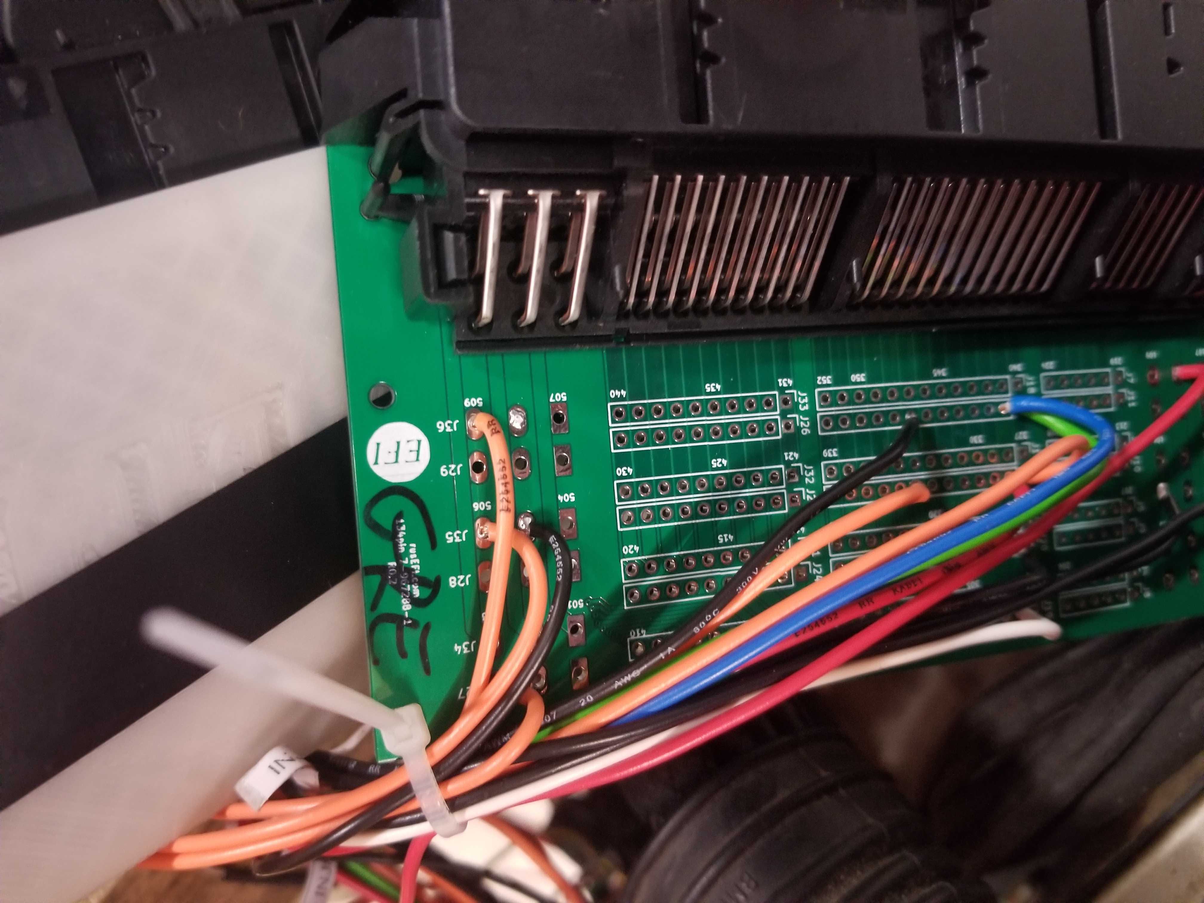
~6 wires are different between Proteus 0.2 and Proteus 0.3+ - all on the 23 pin plug.
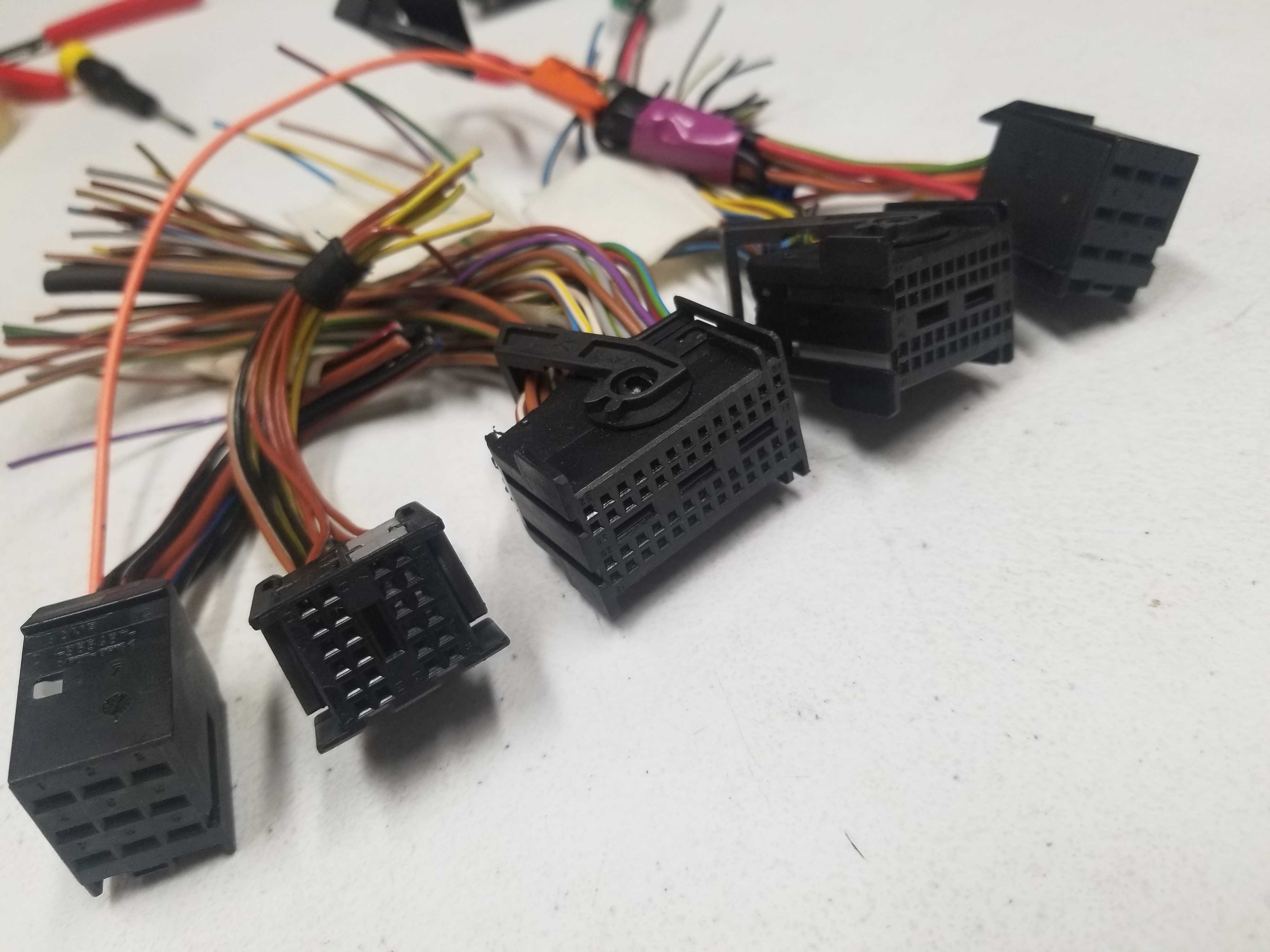
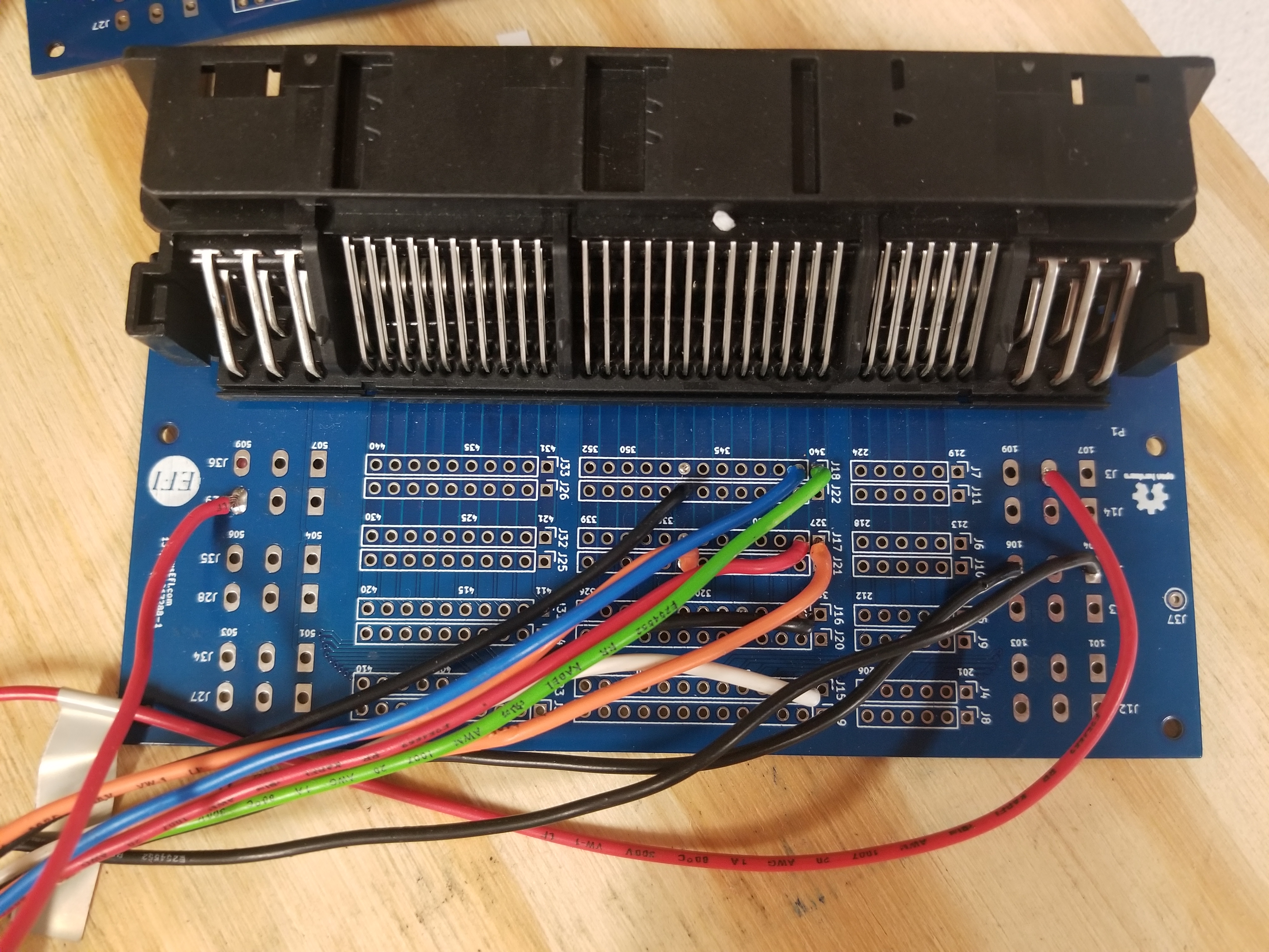
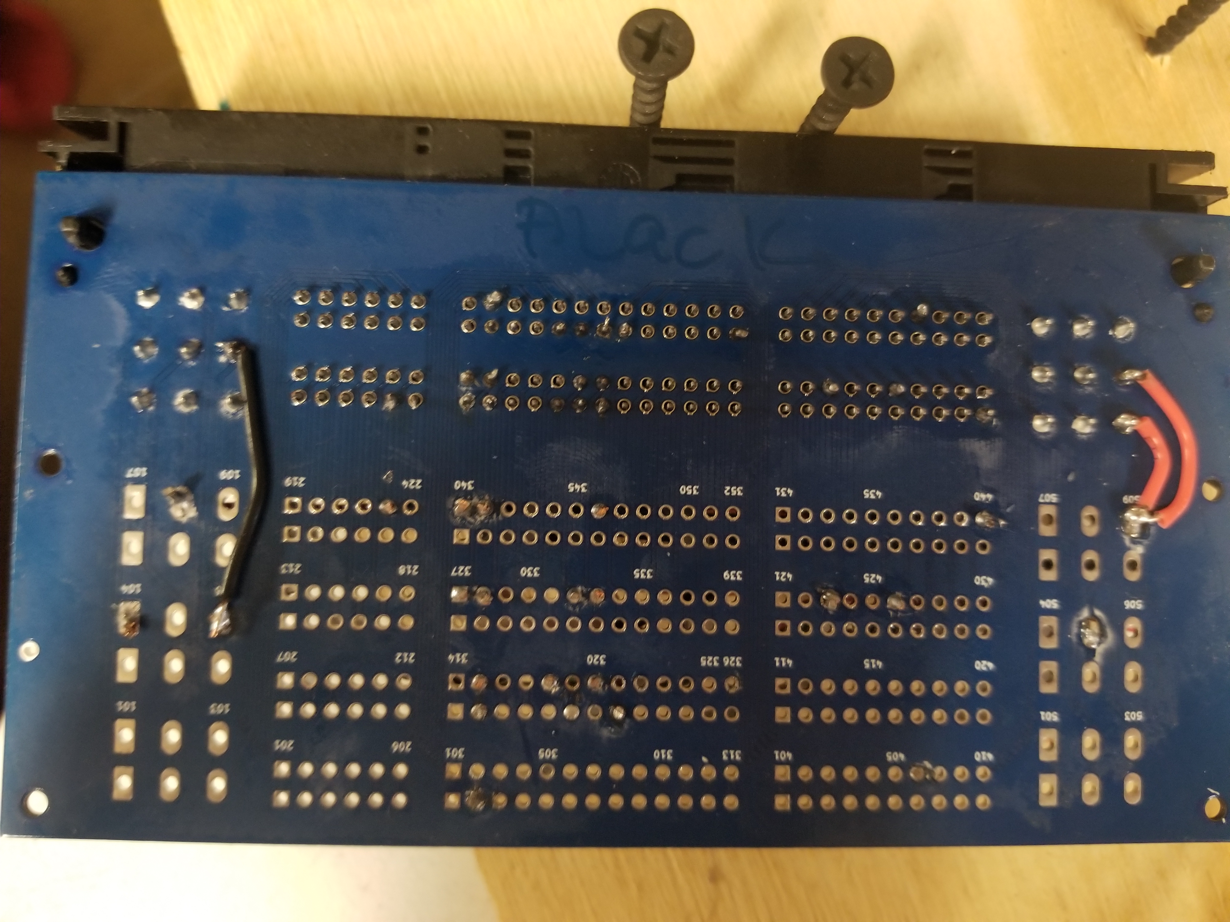
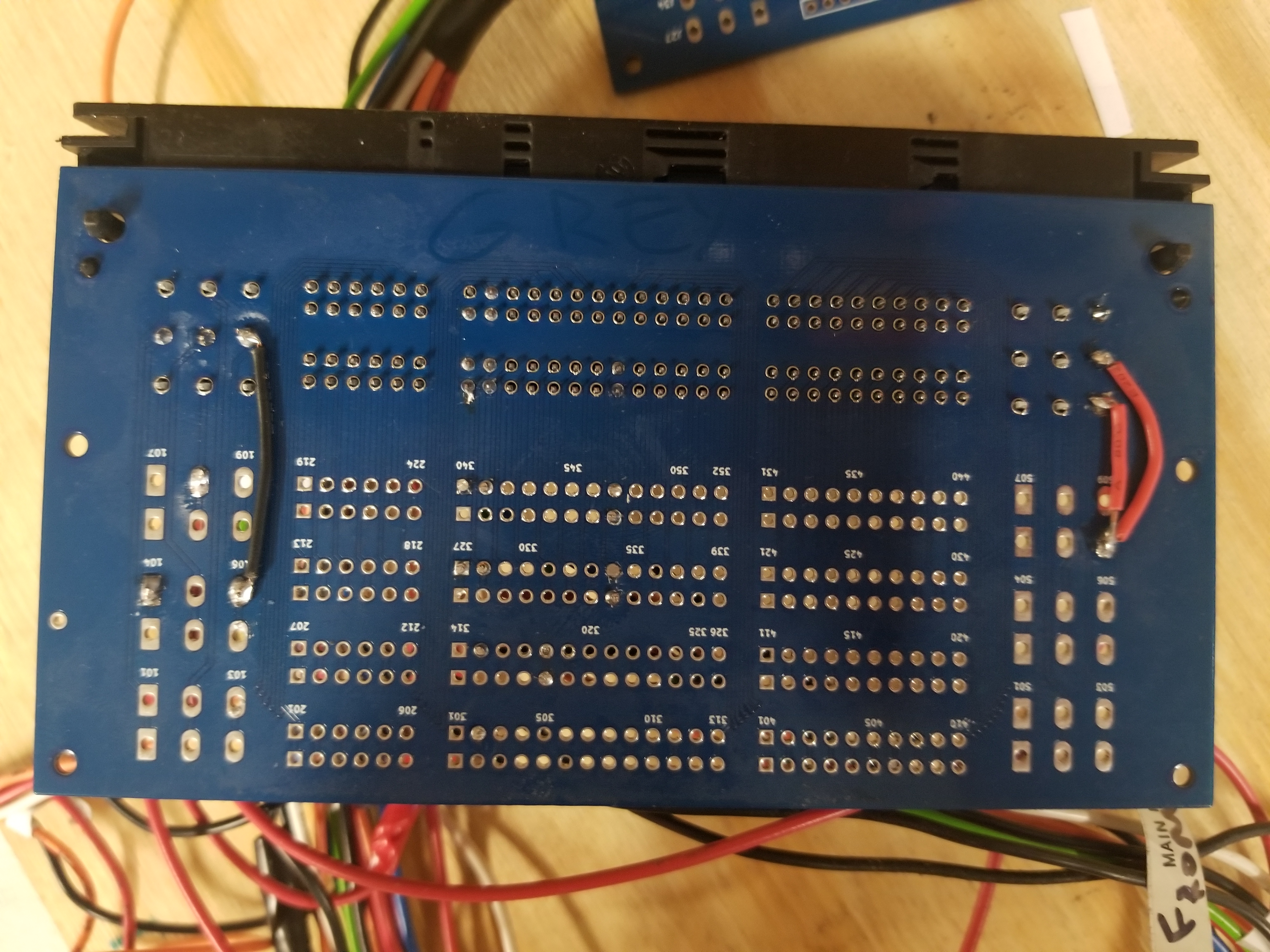
This HOWTO is focusing on M73 engine with stock ECU harness. 1998 stock ECU harness has two 134 pin connectors.
On my 1998 first set of 9+24+52+40+9=134 pins total is BLACK.
Second set of 9+24+52+40+9=134 pins total is GREY.
rusEFI uses six wire colors: black white red orange green blue.
- +12 from main relay
- x12 injectors
- CLT
- IAT
Total wires between Proteus and GREY - 10 Total wires between Proteus and BLACK - 22
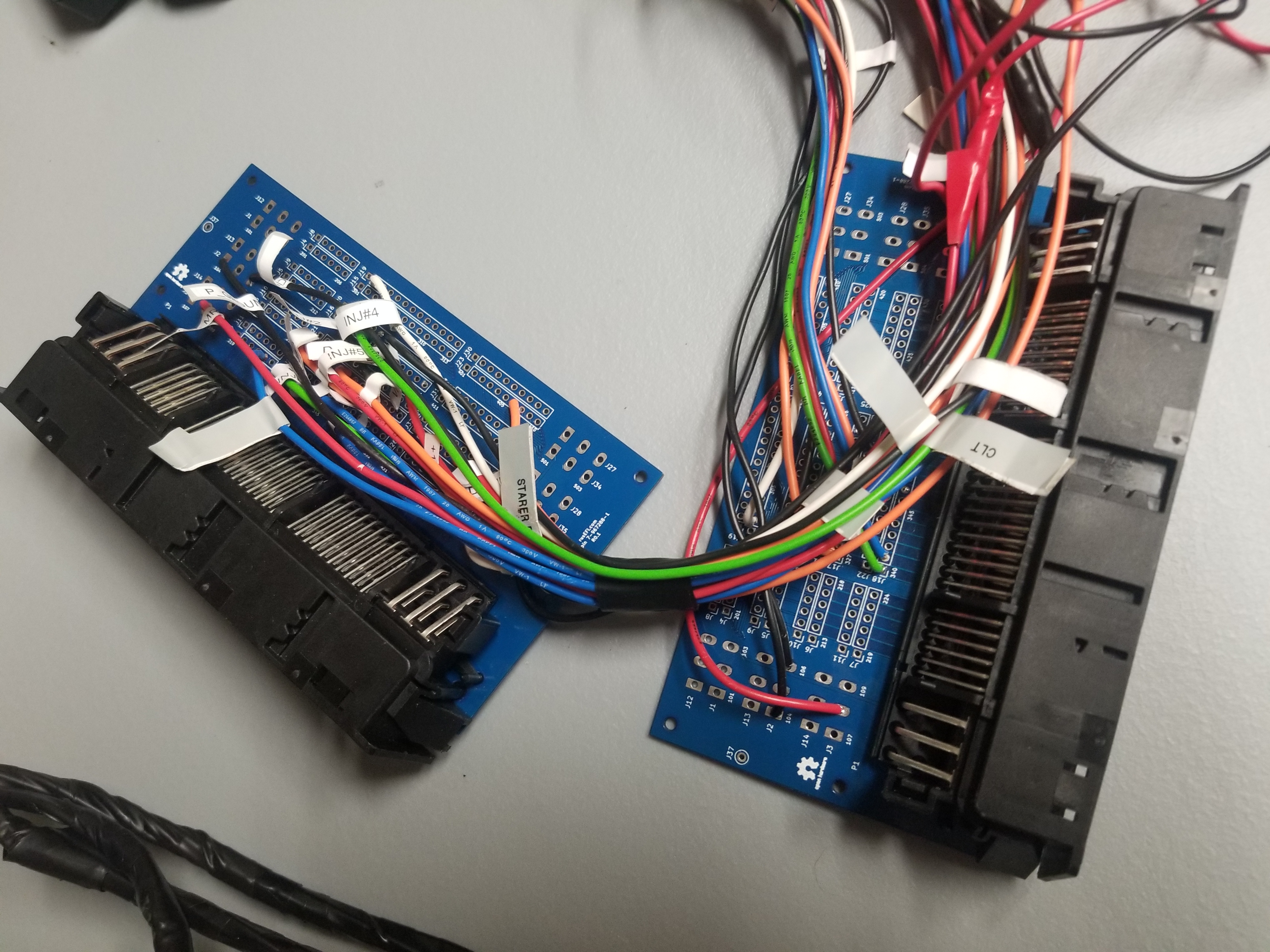
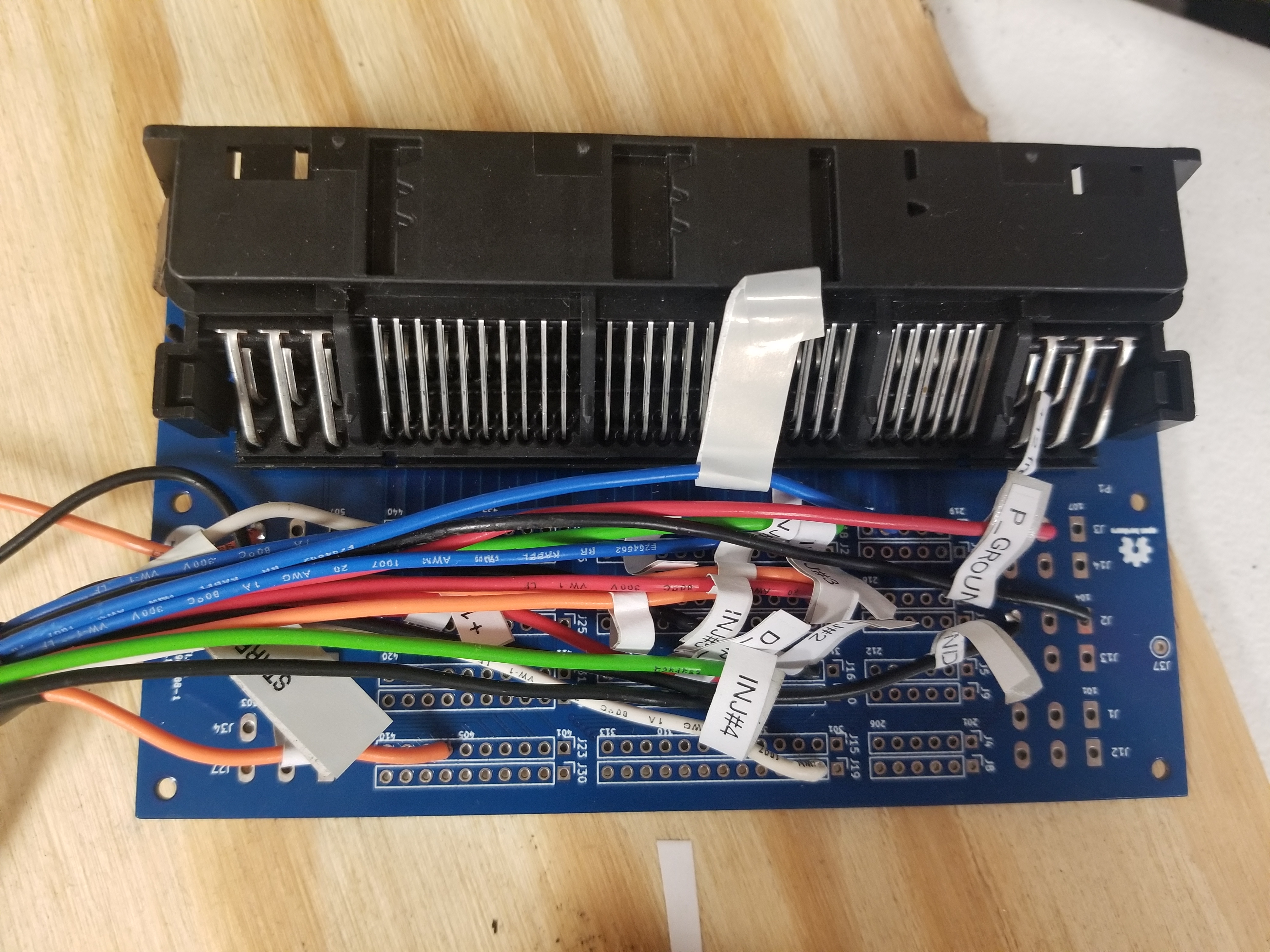
Destination legend: "Black #3 40/52" means "Black set of ECU plugs, connector #3 - pin 40 of 52 total pins"
| Pin Number | Name | Type ID | Default function | rusEFI color | new color | Destination |
|---|---|---|---|---|---|---|
| 3 | Lowside #1 | ls | Injector #1 | Blue | PURPLE | Black #3 41/52 BRN/WHT |
| 4 | Lowside #3 | ls | Injector #3 | Green | YELLOW | Black #3 40/52 |
| 5 | Lowside #5 | ls | Injector #5 | Red | PINK | Black #3 28/52 |
| 6 | Lowside #6 | ls | Injector #6 | Orange | ORANGE | Black #3 27/52 BRN/BLK |
| 7 | Lowside #7 | ls | Injector #7 | Blue | PURPLE | Grey #3 41/52 BRN/WHT |
| 8 | Lowside #9 | ls | Injector #9 | Green | YELLOW | Grey #3 40/52 |
| 9 | Lowside #11 | ls | Injector #11 | Red | PINK | Grey #3 28/52 |
| 10 | Lowside #13 | ls | low-side output: main relay | Blue | PURPLE | Black #2 23/24 BRN/BLK |
| 11 | Lowside #14 | ls | low-side output: starter enable | White | WHITE | Black p #4 40/40 YEL/BRN |
| 12 | Lowside #15 | ls | low-side output: radiator fan relay | green | YELLOW | accessory |
| 15 | Lowside #2 | ls | Injector #2 | Black | BROWN | Black #3 15/52 |
| 16 | Lowside #4 | ls | Injector #4 | White | WHITE | Black #3 2/52 |
| 17 | GND | y | Power GND | Black | BROWN | Grey #1 4/9 |
| 18 | GND | y | Power GND | Black | BROWN | Black #1 4/9 |
| 19 | Lowside #8 | y | Injector #8 | Black | BROWN | Grey #3 15/52 |
| 20 | Lowside #10 | y | Injector #10 | White | WHITE | Grey #3 2/52 |
| 21 | Lowside #12 | y | Injector #12 | Orange | ORANGE | Grey #3 27/52 BRN/BLK |
| 23 | Lowside #16 | y | low-side output: fuel pump | Orange | ORANGE | accessory |
| 24 | GND | y | Power GND | Black | BROWN | Grey #1 6/9 BRN |
| 30 | Ignition 7 | y | Ignition cylinder 7 | White | WHITE | |
| 35 | Ignition 1 | y | Ignition cylinder 1 | Orange | ORANGE |
Unused pins are - 1;2;13;14;25;26;27;28;29;31;32;33;34;
| Pin Number | Name | Type ID | Default function | rusEFI color | OEM connector |
|---|---|---|---|---|---|
| 1 | DIGITAL 2 | din | Camshaft position sensor | Red | Black #3 20/52 |
| 2 | DIGITAL 3 | din | Start button | Orange | accessory |
| 5 | VR1 pos | vr | Variable Reluctance #1 positive | Orange | Black #3 32/52 |
| 8 | ETB1- | y | ETB 1 negative | White | |
| 13 | VR1 neg | vr | Variable Reluctance #1 negative | Blue | Black #3 46 /52 |
| 15 | ETB1+ | etb | ETB 1 positive | Blue | |
| 18 | +12 raw | 12v | ignition power / ECU power source | Red | Black #4 26/40 GRN/BLK |
| 19 | GND | y | Power GND | Black | Black #1 6/9 BRN |
| 21 | ETB2- | etb | ETB 2 negative | White | |
| 22 | ETB2+ | etb | ETB 2 positive | Blue | |
| 23 | +12V mr | 12v | ETB/high-side power supply from main relay | Red | Black #1 8/9 RED/BLU |
| End of Black Proteus 0.2 23 pin table |
| Pin Number | Name | Type ID | Default function | rusEFI color | new color | OEM connector |
|---|---|---|---|---|---|---|
| 1 | DIGITAL 2 | din | Camshaft position sensor | Red | PINK | Black #3 20/52 |
| 2 | DIGITAL 3 | din | Start signal from ignition key | Orange | ORANGE | |
| 5 | VR1 pos | vr | Variable Reluctance #1 positive | Orange | ORANGE | Black #3 32/52 |
| 6 | ETB1- | y | ETB 1 negative | White | WHITE | |
| 7 | ETB1+ | etb | ETB 1 positive | Blue | PURPLE | |
| 8 | ETB2- | etb | ETB 2 negative | White | WHITE | |
| 13 | VR1 neg | vr | Variable Reluctance #1 negative | Blue | PURPLE | Black #3 46 /52 |
| 15 | ETB2+ | etb | ETB 2 positive | Blue | PURPLE | |
| 16 | CAN- | can | CAN bus low | White | WHITE | accessory |
| 17 | CAN+ | can | CAN bus high | Red | PINK | accessory |
| 18 | +12 raw | 12v | ignition power / ECU power source | Red | PINK | Black #4 26/40 GRN/BLK |
| 19 | GND | y | Power GND | Black | BROWN | Black #1 6/9 BRN |
| 23 | +12V mr | 12v | ETB/high-side power supply from main relay | Red | PINK | Black #1 8/9 RED/BLU |
| End of Green Proteus 0.3+ 23 pin table |
Unused pins are - 3;4;;9;10;11;12;14;20;21;22;
| Pin Number | Name | Type ID | Default function | rusEFI color | new color | OEM connector |
|---|---|---|---|---|---|---|
| 1 | GND | sgnd | Sensor GND | Black | BROWN | Black #3 21/52 BRN |
| 2 | GND | sgnd | Sensor GND | Black | BROWN | ETB #1 sensor GND |
| 3 | GND | sgnd | Sensor GND | Black | BROWN | ETB #2 sensor GND |
| 4 | GND | sgnd | Sensor GND | Black | BROWN | Grey #3 47/52 BRN |
| 5 | GND | sgnd | Sensor GND | Black | BROWN | Throttle Pedal Position GND #1 |
| 6 | GND | sgnd | Sensor GND | Blue | PURPLE | Throttle Pedal Position GND #2 |
| 7 | GND | sgnd | Sensor GND | Black | BROWN | Accessory / MAP gnd |
| 8 | GND | sgnd | Sensor GND | BROWN | Black #3 50/52 Knock Shield/GND | |
| 9 | 5V SENS 1 | 5v | Analog Voltage +5 supply #1 | Red | PINK | ETB #1 sensor +5v feed |
| 10 | 5V SENS 2 | 5v | Analog Voltage +5 supply #2 | Red | PINK | Throttle Pedal Position +5v feed #1 |
| 14 | AV3 | av | Analog Voltage Input #3 | Orange | ORANGE | TPS1 Secondary signal |
| 15 | AV5 | av | Analog Voltage Input #5 | Orange | ORANGE | TPS2 Secondary signal |
| 16 | AV7 | av | Analog Voltage Input #7 | White | White | Throttle Pedal Position #2 signal |
| 21 | 5V SENS 1 | 5v | Analog Voltage +5 supply #1 | Orange | ORANGE | Throttle Pedal Position +5v #2 |
| 22 | 5V SENS 2 | 5v | Analog Voltage +5 supply #2 | Red | PINK | Accessory / MAP +5V feed |
| 23 | GND | sgnd | Sensor GND | ORANGE | Grey #3 37/52 Knock Shield/GND | |
| 24 | AV2 | av | Analog Voltage Input #2 | Green | YELLOW | TPS1 Primary signal |
| 25 | AV4 | av | Analog Voltage Input #4 | Green | YELLOW | TPS2 Primary signal |
| 26 | AV6 | av | Analog Voltage Input #6 | Green | YELLOW | Throttle Pedal Position #1 signal |
| 27 | AV8 | av | Analog Voltage Input #8 | Blue | PURPLE | MAP/MAF accessory |
| 28 | AV10 | av | Analog Voltage Input #10 | Green | YELLOW | AFR/WBO accessory |
| 30 | AT2 | at | Intake air temperature IAT | Orange | ORANGE | Grey #3 34/52 |
| 31 | AT4 | at | Coolant temperature CLT | Green | YELLOW | Black #3 22/52 RED/BRN |
| 32 | 5V SENS 1 | 5v | Analog Voltage +5 supply #1 | Red | PINK | ETB #2 sensor +5v feed |
| 34 | knock | Knock #1 | ORANGE | Black #3 49/52 | ||
| 35 | knock | Knock #2 | PURPLE | Grey #3 36/52 |
Unused pins are - 8;11;12;13;17;18;19;20;23;29;34;35;
Wire length:
ETB/Pedal: 7ft/213cm
ECU/OEM pigtails: 52 inches / 132cm
| Color | Quantity on 35 Black |
|---|---|
| Orange | 4 |
| Red | 2 |
| White | 4 |
| Blue | 3 |
| Black | 5 |
| Green | 3 |
| Total | 21 |
| Color | Quantity on 23 Black |
|---|---|
| Orange | 2 |
| Red | 4 |
| White | 3 |
| Blue | 3 |
| Black | 1 |
| Green | 0 |
| Total | 13 |
| Color | Quantity on 35 white |
|---|---|
| Orange | 4 |
| Red | 4 |
| White | 1 |
| Blue | 2 |
| Black | 6 |
| Green | 5 |
| Total | 22 |
| Color | Total Proteus Quantity | Short | Long |
|---|---|---|---|
| Orange | 10 | 7 | 3 |
| Red | 10 | 7 | 3 |
| White | 8 | 5 | 3 |
| Blue | 8 | 5 | 3 |
| Black | 12 | 9 | 3 |
| Green | 8 | 5 | 3 |
| Total | 56 | 38 | 18 |
| Color | Accessory function |
|---|---|
| Orange | Start button |
| White | CAN |
| Red | CAN |
| Red | MAP 5v |
| Black | MAP GND |
| Blue | MAP Signal |
| Green | AFR WBO Signal |
| Green | Radiator Fan Relay |
| Orange | Fuel Pump Relay |
| Pin Number | Name | Type ID | Default function | rusEFI color | OEM connector |
|---|---|---|---|---|---|
| . | |||||
| Pin | type | OEM color | Description | rusEFI color |
|---|---|---|---|---|
| Pin | type | OEM color | Description | rusEFI color |
|---|---|---|---|---|
| Pin | type | OEM color | Description | rusEFI color |
|---|---|---|---|---|
| 6 | IN | start signal from ignition key | ||
| 17 | OUT | BLK | engine speed output for gauge cluster | |
| 26 | IN | GRN/BLK | RED +12v hot in start & run | |
| 40 | OUT | YEL/BRN | BRN starter enable | |
| Pin | type | OEM color | Description | rusEFI color |
|---|---|---|---|---|
| 3 | OUT BLK | ORANGE | coil signal, low-side | |
| 5 | GND BRN | GND | ground | |
| 6 | OUT BLK | ORANGE | coil signal, low-side | |
| 9 | OUT BLK | ORANGE | coil signal, low-side | |
Toyota coil output pin #10 GREEN goes to BLACK breakout
Toyota coil output pin #1 YELLOW goes to GREY breakout
Toyota GND pin #3 goes to both BLACK and GREY breakout #5 5/9
Toyota Battery pin #9 to both BLACK and GREY breakout #1 8/9
- Plug #5 9 pin
- ECU pin 3: OUT BLK RED coil signal, low-side
- ECU pin 5: GND BRN GND ground
- ECU pin 6: OUT BLK RED coil signal, low-side
- ECU pin 9: OUT BLK RED coil signal, low-side
See also the Vault of Electronic Throtttle Bodies
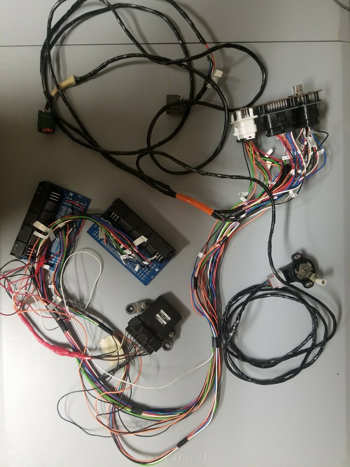
Pictured Proteus with ampseal connectors, non-BMW pedal sensor, two non-BMW ETB connectors, igniter, two breakout boards for the stock connectors.
OEM pedal and ETBs are too unusual thus complete redesign of pedal and ETB hardware and wiring.