Understanding Board Locations
In order for OpenPnP to successfully place a part on a board, it needs to "know" where the part should be positioned on the board, and, just as importantly, it also needs to "know" where the board is positioned on the machine. That first bit of knowledge comes from the CAD database for the board. And the second, from capturing the location of the board using the top (down looking) camera.
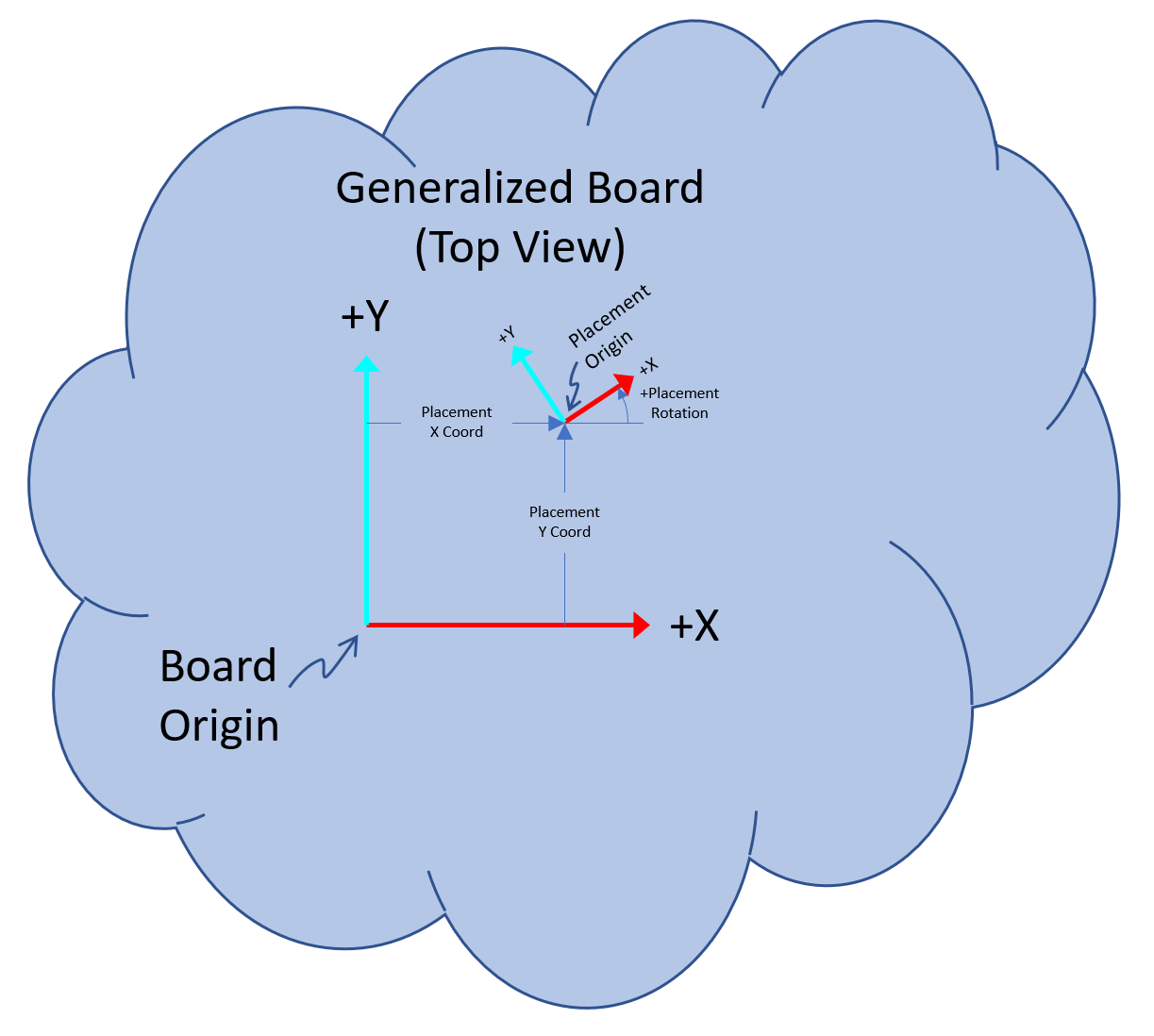
The figure below depicts a generalized board design of no particular shape that may be created with a CAD tool. The board has a coordinate system attached to it denoted by arrows pointing in the positive X-axis (red) direction and in the positive Y-axis (cyan) direction. If the board is moved or rotated, its coordinate system moves with it. When viewed from the top side of the board, the positive Y-axis is 90 degrees counterclockwise from the positive X-axis:
And when viewed from the bottom side, the coordinate system "flips over" with the board and appears as if it was visible though the board. The origins for the two sides are directly opposite from each other and the axes are aligned to point in the same direction as they do on the opposite side. Note that this makes the positive Y-axis 90 degrees clockwise from the positive X-axis.

In addition, each placement also has a coordinate system in which the footprint pads are defined for the part. Note that unlike the board's coordinate system, placement coordinate systems do not mirror for placements on the bottom side - they always have their positive Y-axis 90 degrees counterclockwise from their positive X-axis.
An important point is that both of the above-mentioned coordinate systems are defined in the CAD tool but there are some important considerations on how they should be defined in order to work successfully with OpenPnP:
- OpenPnP expects the origin of each placement's coordinate system to be at the center of the smallest rectangle that encloses all of its footprint's pads. This is the point where OpenPnP will center the nozzle tip on the part when it is being picked. When a board design is imported into OpenPnP, it is the location and orientation of each placement's coordinate system relative to the board's coordinate system that gets imported.
- As mentioned above, OpenPnP also needs to "know" where the board is positioned on the machine. This is accomplished by telling OpenPnP where the origin of the board's coordinate system is located and how it is oriented with respect to the machine. To that end, it is imperative when designing the board, to place its coordinate system such that it is easily identifiable when viewed through the top (down looking) camera. A common practice is to place the origin of the coordinate system at a corner of the board with its axes aligned with the edges of the board. However, in some cases that may not be possible, for example, a round or irregularly shaped board may have no corners or straight edges. In that case, some other visually identifiable feature on the board's surface such as the center of a particular placement, the center a particular pad in a row of pads, or even a special alignment mark either on the outer copper layers or silk screen could be used. It is important, that whatever feature is used, that it provides not only location information (where the intersection of the camera's crosshairs will be placed) but angular information as well (where one or both of the camera's crosshairs will be rotated to align with it). For boards with placements on both sides, the coordinate system must be identifiable when viewed from either side. That is not a problem if using a corner of the board but if some other surface feature is being used, there must be an equivalent feature on the opposite side as well.
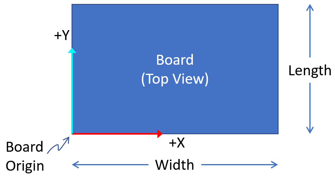
This is by far the most common situation. In the CAD tool, place the origin at the lower-lefthand corner of the board with the positive X-axis aligned along the lower edge and the positive Y-axis along the left edge. In OpenPnP, on the Boards tab, set the width of the board to the X extent of the board and the length of the board to the Y extent of the board:
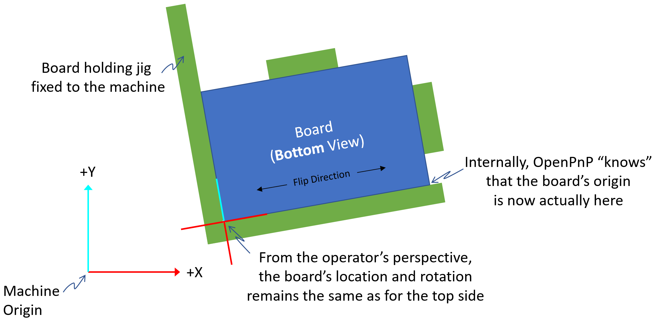
As a practical example of how this is used, the image below depicts a typical situation where a jig attached to the machine is used to hold a rectangular board. As shown in this example, the jig can be mounted at an arbitrary location and rotation relative to the machine coordinate axes. It also shows how the top camera's crosshairs should be aligned for capturing the board's location:

Because the above situation with rectangular boards is so common, OpenPnP makes it easy when flipping a board over to place parts on its opposite side. The rectangular board is just flipped along its X-axis (width dimension), replaced in the jig, and on the Job tab, the Side column is set to the side now facing up. The location and rotation of the board remains the same regardless of which side is facing up on the machine:
Note that while the above discussion pertains to rectangular boards, many other boards shapes can be handled similarly. As long as when the board is flipped and replaced in the jig, the two points defined by the board's origin (0, 0) and the point on its +X-axis that is the width of the board away from the origin (+width, 0) exactly swap places, it will still work. The image below shows a few examples of board shapes where this is true:

Even though OpenPnP is setup to make placing of parts on both sides of rectangular boards easy, it can be used to place parts on both sides of any arbitrarily shaped board with just a little more effort by the operator.
In the CAD tool, place the origin of the board's coordinate system at some convenient location on the surface of the board. As discussed above, be sure that it is located and aligned with some feature on the board so that its location and orientation are easy to identify when viewed through the top camera. If there are placements on both sides of the board, be sure there is an identifiable feature on both sides directly opposite each other so that the origin is visible no matter which side of the board is facing up on the machine.
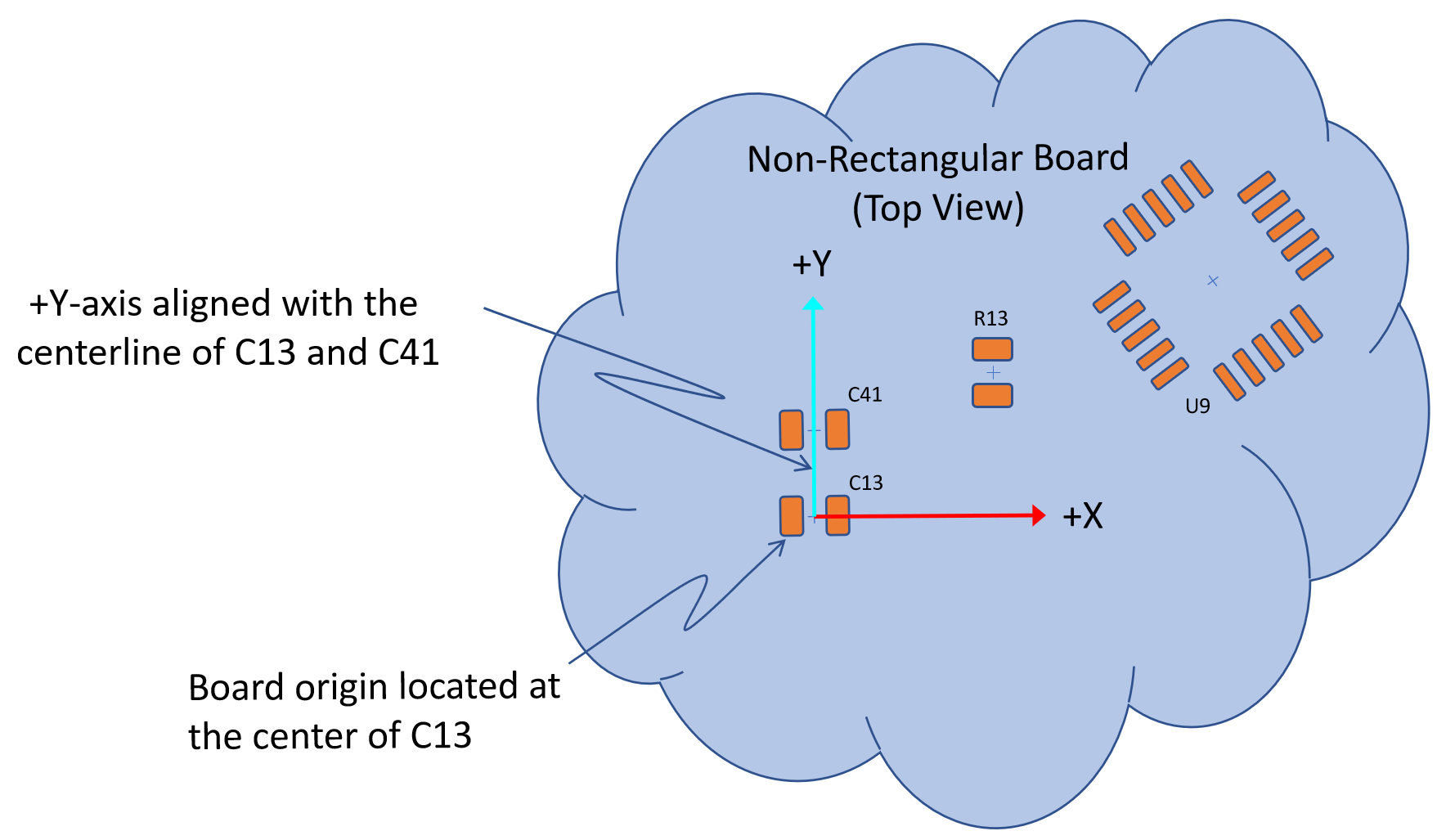
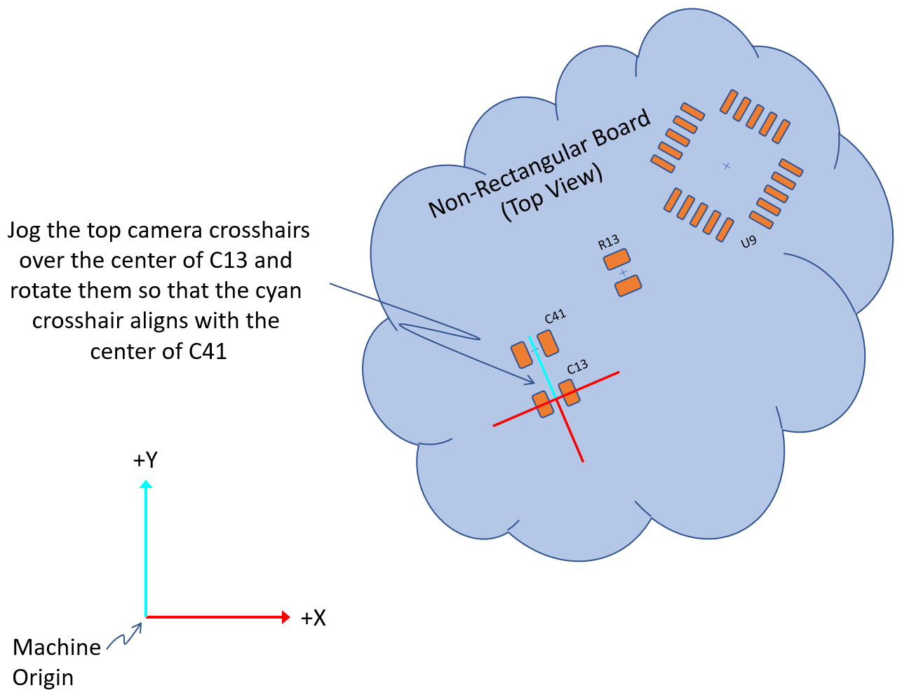
As an example, the board shown below has its coordinate system origin at the center of C13 with its positive Y-axis passing through the center of C41. On its bottom side, U22 has been placed so that its center is directly opposite the center of C13 (on the top side) and rotated so that its pin 1 is aligned with the board's positive Y-axis.
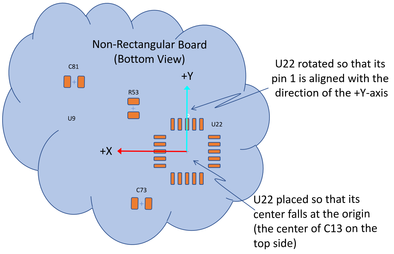
In OpenPnP, on the Boards tab, set the width of the board to zero - this is necessary so that OpenPnP "knows" that the board is not rectangular and will not make any assumptions regarding the location of the board's origin when it is flipped over.
Then, no matter where the board is located and oriented and regardless of which side of the board is placed facing up on the machine, the process for the operator is the same. In OpenPnP, on the Job tab, set the Side column to match the side of the board that is facing up; and, set the board's location by aligning the top camera's crosshairs to the board's coordinate system and capturing its location. This is an important distinction from the rectangular board case - in this case, the location and rotation of the board is in general different for each side and needs to be set after each flip of the board:

Panel locations are handled the same as board locations. Since panels are almost always rectangular in shape, follow the guidelines outlined above for rectangular boards.
 Search the Wiki