Bottom Vision
Bottom Vision is a feature in OpenPnP that makes it possible to place components more accurately. Simply put, by using an up looking camera OpenPnP can identify if a part was picked with any offset or rotational error, determine what that error is and then apply a correction before placement. Bottom Vision can also be used to determine if a pick failure occurred.
The basic idea for bottom vision is:
- Pick a part from a feeder.
- Center the nozzle over an Up looking camera and take an image.
- Using a CvPipeline, determine the part's offset from center and whether or not it is rotated.
- Provide the resulting X, Y and Rotation coordinates to the JobProcessor so that the error can be corrected during placement.
Be sure to have followed Issues and Solutions to have configured and calibrated your machine, cameras, nozzle offsets etc. including notably the Nozzle Tip Background Calibration.
As a further prerequisite, you also need to configure settings on each nozzle tip:

Min. Part Diameter sets the minimum part dimension assumed to be picked with this nozzle tip. This diameter is used to calculate an inner diameter of the nozzle tip that will always be covered by the part (Min. Part Diameter minus two times the Maximum Pick Tolerance). The pixels in the inner diameter are then disregarded/blotted-out by the Background Calibration.
Max. Part Diameter sets the maximum part dimensions (diagonal) assumed to be picked with this nozzle tip. This diameter is used to limit the image area that is taken into consideration. This is also effective as a circular black mask (using MaskCircle). If your camera view has background elements in the periphery that are disruptive to computer vision (there is often some glare), this is a way to cut it off.
Maximum Pick Tolerance sets the maximum allowed distance of the detected part, from its expected location. If it is larger than the given distance, an error will be thrown. This also controls the vision process, by limiting the maximum search distance.
It is recommended to always first try to use the unchanged stock vision settings for bottom vision.
NOTE: If your configurations comes from an older version of OpenPnP, chances are that you are not already using the stock vision settings. One tell-tale is missing sliders in your Bottom Vision Settings. If these are missing, proceed with the following instructions. If they are already there, you can skip ahead to Tuning Bottom Vision.

The following will show you how to select and use them, step by step.
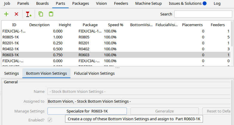
The first step is to try it out with a specific part that you have available for testing. Go to the Parts tab, select that part in the list.
Then back in the list, select the "- Stock Bottom Vision Settings -" in the drop-down in the Bottom Vision column cell. If there are any prior Vision Settings, note them down, so you can revert later.

Go to the Bottom Vision Settings wizard (lower tab), you should get the so-called Exposed Pipeline Parameters, visible as sliders to control the essential parameters of the vision process.
Press the Specialize for XXX button to make a changed setting special for the part (and not affect other parts and packages). This will clone the prior settings it had before.
Pick a part from the feeder and just try it out using a first Test Alignment:
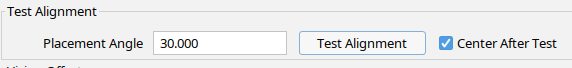
This will perhaps not yet work, but it will move the part to the bottom camera and make sure it is properly lighted. Now you can use the sliders to control the Bottom Vision process.
Threshold sets the minimal brightness that isolates the shiny contacts of a part from the background.
Min. Detail Size sets the minimum size of any details that should still be considered contacts. You can suppress background specks, image noise etc. that might otherwise spoil the detection.
The effect of the tweaking is directly shown in the Camera Preview. As configured in the parameter, the slider previews the Computer Vision pipeline stage that best shows the effect of the adjustments. In addition, if you stop dragging the slider, the computer vision end result is displayed with a slight delay. Watch it in action in the animation:

Using these parameters you should get your bottom vision going in almost all cases.
Use the Test Aligment button again, it should now iteratively center and align the part. The iterative process is controlled by some settings in the Global Configuration explained further below.
Vision Compositing a.k.a. Multi-Shot Bottom Vision can help for parts that are larger than the camera view. Or for other problematic/non-rectangular parts.
If the stock bottom vision and tweaking the parameters does not work for you, here are a few ideas:
-
Double-check the Preparations section above.
-
Check if Camera Settling is configured right.
-
Check if Nozzle Tip Background Calibration was configured right, and is up to date.
-
Perhaps watch this video for a way to let Issues & Solutions help you:
If all this fails, we developers are interested to understand why your case fails, and ask you to contribute your images to the discussion group. To do so, double click your camera view and go to your $HOME/.openpnp2/snapshots directory, where the camera image was saved (see the FAQ for where that directory is on your computer).
If you are pleased with the results and want to use the Stock Bottom Vision Settings more generally, you can make it the system default.
Vision Settings, including the sliders settings, are applied on a multi-level inheritance scheme:
- As the Default (in Machine Setup / Vision), effective for all packages and parts, unless specialized there
- On the Packages level, effective for all parts with that package, unless specialized there
- On the Parts level, effective only for that Part
The idea is to unify and centralize the settings as much as possible in order to make maintenance easier and to easily propagate adjustments to all relevant parts, by inheritance.
If you need special settings on a specific type of package or part, including special** Threshold** or Min. Detail Size slider settings, use the Specialize for XX button as described in Specialize for Package or Part further above.
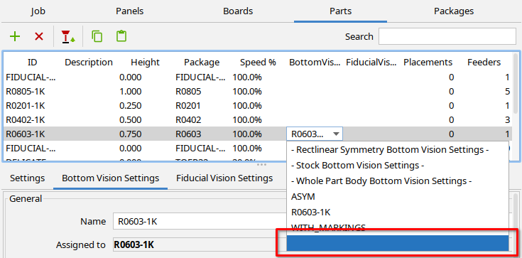
If you want a package or part to inherit the default from the prior level, just unassign the Vision Settings, i.e. select the empty entry:
To understand how this all interacts, you may also want to watch the (somewhat outdated) video:
Core to the working of Bottom Vision is the CvPipeline. The pipeline describes a series of computer vision operations that will take place to convert the input image to a RotatedRect. RotatedRect is computer vision speak for a rectangle (width, height, X, Y) with a rotation component. Using this RotatedRect we calculate the alignment error and correct it.
To configure Bottom Vision visit Machine Setup -> Vision -> Bottom Vision.

Enabled?: Switches on bottom vision.
Bottom Vision Settings: Select the Vision Settings you want as the global default.
Rotate parts prior to vision?: Will already pre-rotate the part on the nozzle to its final placement angle. This generally improves precision. This option also enables adaptive multi-pass vision. The option is mandatory for nozzles that have limited articulation (i.e. less than 360°). It should also be enabled when the PlacementAngle optimization Rotation Mode is set on the nozzle. See Nozzle Rotation Mode.
The part will first be positioned and rotated as picked from the feeder, which means it might be slightly offset both in location and angle, due to play in the feeder etc. The vision operation then determines these offsets, but these may be inaccurate as the part is seen slightly from the side, which may create parallax errors and slight changes in light reflection angles which might affect how beveled/angled surfaces are lighted. Furthermore, the scale in the camera view (units per pixel) might be slightly in error as the part or some of its features (angled pins etc.) might be slightly outside the focal plane.
In order to further improve precision, the part is then centered in the camera view, according to the preliminary offsets and the process is repeated. By centering the part (multiple times), the mentioned errors can be cancelled out by symmetry.
Max vision passes: Determines the maximum number of passes used to pinpoint the part (only applies when pre-rotate is active).
Max linear offset: As long as preliminary linear offsets are larger than this, further passes are made, up until Max. vision passes is reached. Linear offsets are center offsets and corner offsets, see the illustration below. (only applies when pre-rotate is active).
Max angular offset: As long as preliminary angular offsets are larger than this, further passes are made, up until Max. vision passes is reached (only applies when pre-rotate is active).

NOTE: the following is quite outdated, not taking into account the new system of Vision Settings or Exposed Pipeline Parameters.
The following is no longer entirely accurate and left for older versions of OpenPnP.
Each Part in your Parts library can have it's own custom pipeline. In most cases the default pipeline will work but this allows you tweak the pipeline for troublesome parts or create entirely new pipelines when the default won't work.
You can also enable or disable bottom vision on for each part.
To access the bottom vision part settings go to the Parts tab in OpenPnP, select a part and look for the Alignment tab on the right.

Enabled?: Switches on bottom vision for this part. This is checked in addition to the global Enabled? switch (see above).
Pre-rotate: This can either inherit the global setting or override it as Always On or Always Off.

Test: Press the Test Alignment button to perform an alignment of that part. It must already be picked and held on the nozzle.
Center After Test: Centers the part after the vision alignment test.
Pipeline: Press the Edit button to view and edit the part specific pipeline that will be used to locate parts. Press Reset to Default to reset the pipeline to the global default (see Global Configuration).
Rotation: Use the option Adjust for all standard pipelines. Only an adjustment of ±45° can be detected and applied, which is usually more than sufficient for parts picked from normal feeders. Use the option Full only for special pipelines that specifically support full 360° orientation detection (pin 1 detection). CAUTION: You may get very strange and intermittent errors, if you set Full and your pipeline is not specifically made for it.

Part Size Check: You can add a part size check, where the vision result is compared against a known good part size. This can serve as an alternative to vacuum sensing tests, to detect whether a pick was successful.
- Use BodySize if your pipeline looks for the body of the part (e.g. the black body of lead free packages).
- Use PadExtents if your pipeline looks for the contacts (which the default pipeline does). Note, you need to define the footprint in the Package for this to work.

Size tolerance (%): Determines by how much (relatively speaking) the detected part size may deviate from the footprint defined size. If the tolerance is exceeded, the aligment fails. Most likely the part was then not properly picked.
Vision Compositing a.k.a. Multi-Shot Bottom Vision can take more than one vision shot to determine the alignment of a part. See the extra Vision Compositing page.
See https://www.youtube.com/watch?v=pRYQaFKhsuw for a short demonstration of how to pick, test and discard a part for bottom vision.
When bottom vision is enabled in Machine Setup and for a specific part it will be used automatically during a job run. If the system is able to determine the offsets they will be applied. If the operation fails the placement will continue with no offset correction. This will be improved in the future to handle retry and discard.
OpenPnP comes with a default pipeline. The pipeline was developed for one particular machine design but using the CvPipeline tools it is possible to customize the pipeline for any type of machine. In general, the changes should be minimal if certain rules are followed. If you have not read CvPipeline it's worth taking a moment to do so as it will help you understand the rest of this.
The default pipeline is described below:
- ImageCapture: Waits for the camera to settle and captures an image.
- ImageWriteDebug: Writes the input image to a file on disk to help with debugging.
- BlurGaussian: Performs minor blurring on the input image. This is used to reduce noise in the image.
- MaskCircle: Blacks out everything outside of a circle of a given diameter. On the development machine this circle represents a "safe" area in the image where nothing is visible except the nozzle.
- ConvertColor: Convert from RGB color to HSV color, which is required for the next stage.
- MaskHsv: Searches the image for any pixels that match a certain hue (the H in HSV) and turns them black. The purpose of this is to remove green and "greenish" pixels from the image. Green is the color of the nozzle holder. This is similar to the concept of "green screening". See also the Nozzle Tip Background Calibration.
- ConvertColor: Convert back from HSV to RGB. This is required by the next stage.
- ConvertColor: Convert from RGB to grayscale.
- Threshold: Turns the image into a binary image - meaning that it has only two colors: white and black. Any gray pixels that are darker than the threshold value turn black and any lighter turn white.
- FindContours: Find connected contours in the image. Contours are a way to describe simple features in an image such as lines and curves.
- FilterContours: Removes any contours from the previous stage that are smaller than a specified value. This helps remove noise and features that don't pertain to the main contour around the part.
- SetColor: Sets the entire image to black. This simply provides a blank canvas for the next stage to draw on.
- DrawContours: Draw all the of the remaining contours in white on the black background. At this point we hope that we're simply drawing the shape of the part only.
- MinAreaRect: This is where the magic happens! MinAreaRect creates a
RotatedRectthat fits around any non-black pixels in the image. Since we drew contours representing the part this now finds the bounds and rotation of the part. - ImageRecall: Recalls the original input image so that we can show the user the results of all this work.
- DrawRotatedRects: Draw the
RotatedRectin red overtop the recalled original image. If all went well we should now see the original input image with a red rectangle surrounding the part. - ImageWriteDebug: Writes the resulting image out to a file for help with debugging.
-
Much of the purpose of the vision pipeline is to filter the image so that the only thing that is visible is the part you are interested in. The various Mask stages and Thresholds can help with this.
-
Switch off the camera's auto-exposure. Otherwise, this will never be stable and repeatable. If your camera does not allow that, chose a different model. Seriously.
-
You should set your Camera's exposure, so you the dynamic range includes the brightest parts of the image without clipping. We need to be able to distinguish the bright tones. Use the shiniest part to set this up. The image will be rather dark for humans, but it is fine for machine vision.
-
The following animation quickly shows you how to initially set or tune a threshold, using the mouse to probe image pixels. Look at the third channel (the
V) of theHSV(full)indicator on the status line (this indicator for brightness will work both for color and grayscale images). Probe the pixels that should be excluded and probe the pixels that should be included, then set the threshold to a value in between:While holding down the Shift key, use the context menu to display the image separately. This will restart the animation from the beginning.

-
If you have green color Juki nozzle tips you can use the MaskHSV stage to mask the green parts reliably. Make yourself familiar with the HSV model (from the Wikipedia).

-
The following animation quickly shows you how to initially set or tune an HSV mask, using the mouse to probe image pixels. First we probe green pixels and look at the first channel (the
Has in "hue") of theHSV(full)indicator on the status line to include what is green. Then we exclude parts that are too bright (the pins) looking at the third value (theVas in "value" i.e. brightness) of theHSV(full)indicator on the status line. Finally, we exclude the parts that are too dark (background stuff, the IC body), using the same method.While holding down the Shift key, use the context menu to display the image separately. This will restart the animation from the beginning.

Enable DEBUG or TRACE level logging. See this FAQ for more information. Bottom vision will now produce a pair of debug images in your .openpnp/org.openpnp.vision.pipeline.stages.ImageWriteDebug directory.
 Search the Wiki