Central Processing Unit (CPU) - KS10FPGA/KS10FPGA GitHub Wiki
The CPU module is a big module that glues all of the CPU subsections together. The subsections are illustrated below in the block diagram.

CPU Block Diagram
The CPU Code is located in the repository at: https://github.com/KS10FPGA/KS10FPGA/blob/master/fpga/ks10/cpu/cpu.v
The DEC KS10 ALU implementation used ten cascaded AM2901 4-bit processor slices. Some quick study showed that this did not work well with an FPGA implementation. Most FPGAs have optimized (very fast) carry logic that is provided to support counters and adders. This carry logic is much faster than the AM2902 parallel carry devices that supported the AM2901 slices in the KS10.
It turns out that the Verilog (and VHDL) synthesis tools could not infer that there was a single 40-bit carry chain from the Register Transfer Logic (RTL) description of the ten cascaded 4-bit slices. The resulting ALU was very slow.
A complicating architectural features of the PDP-10 ALU is the requirement to operate as a single 36-bit ALU or to operate as two independent 18-bit ALUs with no carry between the lower 18-bits and upper 18-bits. In order to accomplish this, the DEC engineers inserted an “AND Gate” in the middle of the carry chain to implement this feature. Again, this limits the speed of the ALU. A block diagram of the DEC KS10 ALU is illustrated below.

DEC KS10 ALU Implementation
In the FPGA implementation, maintaining the integrity of the carry chain is very important to the speed of the ALU. To that end, the KS10 FPGA ALU is implemented both ways: as a single 40-bit wide ALU and as two independent 20-bit ALUs. Gates are cheap. The two different types of operations occur in parallel and the correct output is selected at the module output. Instead of the microcode enabling the carry between the two halves of the ALU, the microcode selects between the 40-bit ALU with the carry between the two halves and the 40-bit ALU with no carry between the two halves. This is illustrated below.

KS10 FPGA ALU Implementation
This saves ‘cutting’ the 40-bit ALU carry chain in the middle and maintains the ALU speed.
This design change actually makes the description of the KS10 FPGA much simpler than the alternative. The operation of the 40-bit Q-shifter and the 40-bit F-shifter is much more visible than in the original DEC KS10 design.
So why is the ALU 40-bits wide instead of 36-bits?
Notice that the ALU is sign extended by two bits on the left, and zero padded by two bits on the right. The ALU is implemented with 4-bit wide slices. This implementation gave the DEC hardware access to the CRY2 (Carry 2) signal which is available at the interface between the first and second ALU chip. If this was implemented as a 36-bit wide ALU, this signal would be buried inside the am2901 chip and not accessible. There may be other signals also.
The FPGA implemented the CRY2 output completely differently.
The ALU Code is located in the repository at: https://github.com/KS10FPGA/KS10FPGA/blob/master/fpga/ks10/cpu/alu.v
The CPU Backplane Interface is the interface between the CPU and the backplane peripherals. The major function of the backplane is to determine the KS10 addressing mode. The KS10 understands four addressing modes. Namely:
- Extended Address – This is a full 20-bit address
- Physical Address – This is a 18-bit address
- Paged Address – This is a 20-bit virtual address
- WRU Address – A "Who Are You (WRU)" cycle is part of the interrupt acknowledge bus cycle. It addresses whatever device is asserting the highest priority interrupt request

Extended Address

Physical Address

Paged Address

WRU Address
The Bus Address Multiplexer is simply a 36-bit wide 4-input multiplexer as illustrated below.
The Bus Interface Block diagram is illustrated belo

Bus Interface Block Diagram
The Bus Interface Code is located in the repository at: https://github.com/KS10FPGA/KS10FPGA/blob/master/fpga/ks10/cpu/bus.v
The DBM Mux is used to access the SCAD, Timer, VMA Register, Bus Interface, and the Number field of the microcode. It can perform left-half/right-half bus swap and it is also used to do hardware byte selection when the byte is exactly 7 bits.
The DBM Mux is controlled by the microcode DBM Select (DBM_SEL) field, the byte select mux is controlled by the microcode SPECIAL (DBM_SPEC) field.
The DBM Block diagram is illustrated below.
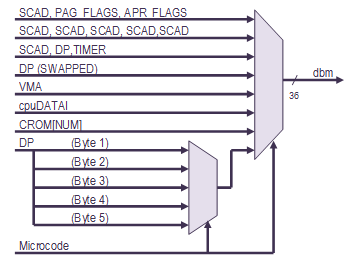
DBM Block Diagram
The DBM Code is located in the repository at: https://github.com/KS10FPGA/KS10FPGA/blob/master/fpga/ks10/cpu/dbm.v
The DBUS module is essentially a 36-bit wide 4-to-1 multiplexer. The DBUS multiplexer selects between the FLAGS, the ALU Output (DP), the DBM Multiplexer, and the RAMFILE. On a memory read operation, the DBUS Multiplexer also selects between the RAMFILE (where the ACs are stored) if an AC is being read and memory if an AC is not being read.
When a memory request is made, the memory contents are supplied to this block via the DBM input. When a memory request is made to one of the AC registers, the forceRAMFILE bit is asserted and the contents of the RAMFILE is selected instead of the memory contents.
The forceRAMFILE signal is implemented very differently than the DEC KS10. In the KS10 FPGA implementation, the forceRAMFILE signal is asserted when the KS10 Bus input to the DBM Multiplexer is selected (i.e., during a memory read) and the VMA points to one of the ACs. That is VMA[18:31] is zero.
The Block Diagram of the DBUS Multiplexer is illustrated below .
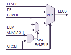
DBUS Block Diagram
The DBUS Code is located in the repository at: https://github.com/KS10FPGA/KS10FPGA/blob/master/fpga/ks10/cpu/dbus.v
The microsequencer is a device that sequences through the microcode. The microsequencer has various inputs that control the execution sequence but the only output from the microsequencer block is the Control ROM (CROM) which provides the KS10 microcode. This microcode is used to control the various blocks of the KS10 hardware.
The DEC KS10 CPU was implemented using 2048 words of 108-bit wide horizontal microcode (as opposed to vertical microcode). The microarchitecture supports 12-bit addressing of microcode (4096 words) but the DEC KS10 only implemented 2048 words microcode. The KS10 FPGA implements all 4096 words of microcode.
The microcode begins execution at address 0000. The microsequencer continuously re-executes instruction at address 0000 while the RESET signal is asserted and will only execute the next instruction after the RESET signal has been negated. This design assumes that the RESET negation is synchronized to the clock and that the RESET signal is asserted for a few clock cycles minimum to ensure that the instruction at address 0000 has been executed at least once.
The Page Fail hardware is hard coded to vector to the Page Fail handler address. The Page Fail vector hardware is a bunch of “OR Gates” which just assert all of the microcode ROM address bits - therefore the Page Fail handler is located at 3777 (octal) for the DEC KS10 and 7777 (octal) for the KS10 FPGA. In general, the hardware addressing (Reset, Page Fail, Skip, and Dispatch) must match the addresses in the microcode. Therefore the hardware cannot be modified without appropriate changes to the microcode
The addressing the microsequencer is very minimalistic. Whereas a modern implementation might use a multiplexer to control the addressing, the KS10 uses simple “OR” gates. Therefore the SKIP, DISPATCH, and PAGE FAIL logic can only modify the addressing by setting bits – never clearing address bits.
On a normal microcode instruction, the SKIP, DISPATCH, and PAGE FAIL addresses are zero. The Control ROM supplies the next address from the microcode “Jump” field.
When a SKIP is to be performed (a primitive conditional branch-like instruction), the SKIP entity conditionally supplies an address of 0000 or
- This conditionally sets the LSB of the address. Of course the microcode must be designed such that the two destination addresses are appropriate.
The DISPATCH is similar to a SKIP except that an N-way branch can be executed. Again, the microcode must be designed such that all of the possible destination addresses are correct. The microcode uses a 512-way branch to quickly decode instruction opcodes, and additional N-way branches to quickly decode addressing modes. The opcode dispatch address is provided by the Dispatch ROM (DROM).
A block diagram of the Microsequencer is illustrated below.
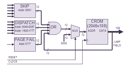
Microsequencer Block Diagram
The major modules that implement the Microsequencer are detailed in the following sections.
The Microsequencer Code is located in the repository at: https://github.com/KS10FPGA/KS10FPGA/blob/master/fpga/ks10/cpu/useq/useq.v
The dispatch logic allows the microcode to perform an N-way branch based on a set of inputs. Implementation wise, it is a large multiplexer that is controlled by the microcode that provides a 12-bit dispatch address output.
The multiplexer is broken into two halves: the upper 8-bits are controlled independently from the lower 4-bits. This segregation into halves provides many 16-way dispatches and a few larger (up to 512-way) dispatches.
The instruction opcode decode dispatch is a 512-way dispatch where the address is supplied by the dispatch ROM.
The DEC KS10 dispatch logic was fairly convoluted (and very difficult to understand) in order to minimize logic and limit the size of the Dispatch ROM. For example, the instruction opcode decode dispatch is constrained to be in the address range between 1400 (octal) and 1700 (octal) in the microcode. The DEC KS10 design used a lot of hardwired logic to generate addresses in this address range - only the least significant bits were stored in the Dispatch ROM. In the KS10 FPGA, the entire dispatch address is stored in the dispatch ROM which significantly simplifies the logic description.
The logic synthesis tool is ‘smart enough’ to determine that the data contents of those ROM bits is constant for all addresses, remove the data from the ROM, and replace the ROM contents with hardwired logic just like the DEC KS10 – except that the design intent is much more evident in the FPGA version.
Obviously the design of dispatch logic and the design of the microcode must be compatible.
The Microsequencer Dispatch Code is located in the repository at: https://github.com/KS10FPGA/KS10FPGA/blob/master/fpga/ks10/cpu/useq/dispatch.v
The skip logic provides a means for the microcode to perform a conditional jump operation based on a boolean value. For the most part, the SKIP logic is a big 24:1 multiplexer that generates this boolean value.
The skipADDR output is always either 0000 (octal) for “no skip” condition or 0001 (octal) for a “skip” condition. Skips always occur from even addresses to odd addresses because the SKIP block addressing is implemented with an "OR Gate". It is not a multiplex operation
The Microseqencer Skip Code is located in the repository at: https://github.com/KS10FPGA/KS10FPGA/blob/master/fpga/ks10/cpu/useq/skip.v
This microsequencer stack provides a mechanism for the microcode to ‘call’ and ‘return’ from microcode subroutines.
The microsequencer stack is implemented quite a bit differently than the KS10 simply because the FPGA provides Dual Port RAMs.
- The addrOUT 'read' port of the Dual Port RAM provides the return address. This port always points to the top-of-stack and can always be read independently.
- The addrIN 'write' port of the Dual Port RAM is used to store the next 'call' address. This port always points to the address past the top-of-stack and can always be written independently.
A block diagram of the microseqencer stack is illustrated below.

Microseqencer Stack
When the ‘call’ input to the block is asserted, the 'call' address is stored, the stack pointer is incremented and the return address automatically becomes available at the new top-of-stack.
When the ‘ret’ (return) input to the block is asserted, the stack pointer is decremented. The return address is always available at the addrOUT[0:11] port.
This implementation saves all the KS10 logic to dynamically change RAM address depending if a 'call' or 'return' instruction is being processed. It also allows the stack to always update in a single clock cycle.
The ‘call’ and ‘return’ operation of the microcode is quite a bit different than modern computers. The microsequencer stores the address of the ‘call’ instruction on the stack. The microcoded ‘return’ instruction must include a dispatch offset to the address in order to return to an instruction after the ‘call’ instruction.
When a Page Fail exception occurs, the microcode vectors to the ‘Page Fail’ handler - and simultaneously asserts the 'call' input. When the Page Fail handler code has completed execution, the microsequencer returns to the microcode instruction (the read or write operation that caused the Page Fail exception) and re-executes that instruction.
The Microseqencer Stack Code is located in the repository at: https://github.com/KS10FPGA/KS10FPGA/blob/master/fpga/ks10/cpu/useq/stack.v
The Control ROM contains the executable microcode of the microsequencer.
This module of the KS10 FPGA microsequencer is implemented significantly different than the DEC KS10 circuit but performs exactly the same function.
The DEC KS10 implementation has several implementation issues which must be addressed in an FPGA design. These are:
- The DEC KS10 microcode is stored in a RAM which must be loaded by the console processor at power-up. This is complicated and unnecessary. The FPGA can provide ROM for this function.
- The Control RAM is asynchronous. The FPGA provides synchronous memory.
In the KS10 FPGA, the Control RAM is replaced by a synchronous ROM which is not writeable. This simplifies the boot procedure. The Control RAM microcode is post-processed to remove unused fields and rearrange the bits (I assume to optimize the hardware design). For example, the microcode listing defines a 108-bit wide microcode word whereas the hardware is only 96-bits wide. In the KS10 FPGA, the post-processing step has been elided as it is unnecessary. The Verilog synthesis tool is smart enough to identify and remove unused (or constant) data fields in the ROM. Also, the post-processing also adds parity which is not really necessary for the FPGA.
The DEC KS10 microsequencer had a 12-bit address which could have supported 4096 words of microcode; however, only half of the memory was actually implemented in the production hardware. Unfortunately, over time, the microcode grew to be larger 2048 words. When that occured, DEC shipped three version of the microcode – each matching a specific application. When you booted the machine, the boot disk (or tape) had the correct version of the microcode installed so boot process could load the correct microcode into Control RAM.
The various types of microcode are detailed below:
KS10 Microcode Variations |
||
Filename |
Description |
|
KS10.MCR |
Diagnostic microcode.
Includes TOPS10 paging and TOPS20 paging but does not include the UBABLT instructions. |
|
|
T10KI.MCR |
TOPS10 microcode. Includes TOPS10 paging and UBABLT instructions but does not include TOPS20 paging. |
|
T10KL.MCR |
TOPS20 microcode. Includes TOPS20 paging and UBABLT instructions but does not include TOPS10 paging. |
|
CRAM4K.MCR |
*NEW* KS10 FPGA Unified microcode. Includes TOPS10 paging, TOPS20 paging, and UBABLT instructions. The APRID instruction reports 470130_010001 which is decoded below: |
|
Option |
Description |
|
INHCST=1 |
Allow inhibit of CST update if CSB = 0 |
|
NOCST=0 |
Include support for writing the CST |
|
NONSTD=0 |
Standard microcode |
|
UBABLT=1 |
Support UBABLT instructions |
|
KIPAG=1 |
Support KI paging |
|
KLPAG=1 |
Support KL paging |
|
MCV=130 |
Microcode version |
|
HO=0 |
Hardware options |
|
HSN=4097 |
Hardware Serial Number |
|
Fortunately all three versions of microcode were derived from a single codebase using conditional compiles to remove microcode as required.
It was desirable for the KS10 FPGA to have the microcode in ROM. The additional microcode memory allowed the KS10 FPGA to support a functional superset of all of the DEC microcode.
Implementing the new version of microcode only required some minor modifications to the conditional compiles and some new build command files. A small design change was required to move the PAGE-FAIL entry point from 3777 (octal) to 7777 (octal) - which was a hardware constraint.
When a page failure occurs, the PAGE-FAIL address is generated in the hardware by setting all of the microcode address bits to one (using 12 OR gates). In the DEC KS10, the MSB of the address was unused and the microcode was limited to 2048 words, this created a PAGE-FAIL entry point of 3777 (octal) in the microcode. Once the full microcode memory was implemented, the correct entry point of 7777 (octal) was exposed to the microcode.
The Control ROM Code is located in the repository at: https://github.com/KS10FPGA/KS10FPGA/blob/master/fpga/ks10/cpu/useq/crom.v
The microcode output listing is located in the repository at: https://github.com/KS10FPGA/KS10FPGA/blob/master/fpga/ks10/cpu/useq/ks10.mcr
The microcode field definitions of the Control ROM is located in the repository at: https://github.com/KS10FPGA/KS10FPGA/blob/master/fpga/ks10/cpu/useq/crom.vh
The Dispatch ROM maps the instruction (from the Instruction Register) to the address of microcode in the Control ROM that decodes and executes that instruction.
The DEC KS10 implementation of the Dispatch ROM is problematic for an FPGA implementation because the DROM in the KS10 is asynchronous whereas FPGA memories are synchronous.
Fortunately the DROM is addressed by the Instruction Register (IR) - which is loaded synchronously. Therefore the KS10 FPGA absorbed a copy of the OPCODE portion of IR directly into Dispatch ROM addressing. Simply put: When we load the IR, we also simultaneously and synchronously lookup the contents of the Dispatch ROM.
The Dispatch ROM is a 512 x 36 bit synchronous ROM.
The DEC KS10 Dispatch ROM contents (as created by the microcode assembler) is post-processed to remove unused microcode fields and rearrange the bits. In the KS10 FPGA implementation, the Dispatch ROM contents match the format of the microcode listing and the post-processing step is elided. The Verilog synthesis tool is smart enough to remove unused microcode fields from the ROM.
The Dispatch ROM contents are extracted from the microcode listing file by a simple AWK script.
The Dispatch ROM Code is located in the repository at: https://github.com/KS10FPGA/KS10FPGA/blob/master/fpga/ks10/cpu/useq/drom.v
The microcode output listing is located in the repository at: https://github.com/KS10FPGA/KS10FPGA/blob/master/fpga/ks10/cpu/useq/ks10.mcr
The microcode field definitions of the Dispatch ROM is located in the repository at: https://github.com/KS10FPGA/KS10FPGA/blob/master/fpga/ks10/cpu/useq/drom.vh
The KS10 CPU proper provides an 18-bit virtual address space for programs. The Pager provides an address translation mechanism that allows the KS10 CPU to access more than 256K words of memory.
The Pager adds two more bits of addressing which creates a 20-bit physical address from the 18-bit virtual address.
The Pager translates virtual addresses/page numbers to physical addresses/page numbers. There are 512 virtual pages which map to 2048 physical pages.
The address translation is illustrated below:
![]()
Pager Address Translation
Physically, the pager sits between the CPU and the KS10 Backplane Bus on the address bus.
The DEC KS10 Page Translation Memory (Page Tables) were implemented using asynchronous memory which does not translate to an FPGA very efficiently. Since the Page Translation Memory is addressed by the VMA register and the VMA register is loaded synchronously, the FPGA implementation simply absorbs the VMA register into the Page Translation Memory addressing. In other words, when the VMA register is loaded, the VMA address is synchronously loaded into the Page Translation Memory. The Page Table is interleaved with odd and even memories so that the memory can be swept two entries at a time. The Page Table addressing is rearranged from that of the DEC KS10. On the DEC KS10 the two memories are interleaved by the MSB of the address. On the KS10 FPGA, the two memories are interleaved by the LSB of the address. When the interleaving is done this way, the Xilinx synthesis tool can infer a dual port memory with different aspect ratios on the two ports as follows:
- The Page Table is address by the write port as 256 x 30-bit memory. The 30-bit wide write port allows the page memory to be written and swept two entries at a time.
- The Page Table is address by the read port as 512 x 15-bit memory. The 15-bit wide read port allows for simple page lookups.
Referring to the block diagram below, the CPU writes data into the Page Table via the left port of dual port memory. The page translation data which consists of the virtual page number and the page flags is written to the dual port memory two entries at a time. This is consistent with the format of the User Page Tables and the Executive Page Tables. In general, the 'dp' (ALU) bus is the source of the data. The Page Table is also swept two entries at a time. This port is write-only.
On the right port of the dual port memory, the virtual address is used to address the Page Translation Memory. The output of this memory provides the Physical Page Number that is used to build the Physical Address. This port is read-only.

Pager Block Diagram
The Page Flags are:
- Page Valid - this flag indicates that the page information has been initialized.
- Page Writable - this flag indicates that the page can be written.
- Page Cacheable – this flag indicates that the page is cacheable.
- Page User – this flag indicates that the page has only user-mode access privledges.
Note: All page flags are cleared when the Page Table is swept, although clearing the Page Valid flag is sufficient.
The Pager Code is located in the repository at: https://github.com/KS10FPGA/KS10FPGA/blob/master/fpga/ks10/cpu/pager.sv
The KS10 Priority Interrupt Controller is responsible for controlling the KS10 CPU’s response to interrupt requests. The Priority Interrupt Controller maintains a notion of the Current Interrupt Priority, whether an individual interrupt is enabled and whether the Priority Interrupt Controller is enabled.
When an interrupt input is asserted, the interrupt controller determines if the new interrupt is of a higher priority than the current interrupt state. If it is, and interrupt request to the KS10 CPU is made.
The KS10 supports three interrupt sources which are enumerated below:
- Arithmetic Processor (APR) Interrupts
- IO Bus (UBA) Interrupts
- Software Interrupts (Program Requests)
Each of the interrupt sources can provide 7 interrupt requests. Tb he highest interrupt request priority is interrupt 1; the lowest interrupt request priority is interrupt 7.
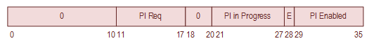
The Priority Interrupt Register state is stored inside the ALU Register 14 (octal). When the “specLOADPI” microcode instruction is executed, the Priority Interrupt Register state is loaded from the ALU into the Priority Interrupt hardware via the DP bus. Notice that the format of the Priority Interrupt Register is closely resembles the operand of the Executive Mode RDPI instruction.
The format of the Priority Interrupt Register is enumerated in the following diagram:
Priority Interrupt Register (Inside ALU)
The block diagram of the Priority Interrupt controller is illustrated below:

Priority Interrupt Block Diagram
The Priority Interrupt code is located in the repository at: https://github.com/KS10FPGA/KS10FPGA/blob/master/fpga/ks10/cpu/pi.v
The RAMFILE contains storage for microcode. This is essentially everything that is not stored in the ALU register set. The microcode does not use any of the KS10 memory.
The RAMFILE is a dedicated chunk of memory which is organized as 1Kx36. The RAMFILE is address as follows:
RAMFILE Addressing |
|
Address (octal) |
Description |
0000-0017 |
AC Block 0 |
0020-0037 |
AC Block 1 |
0040-0057 |
AC Block 2 |
0060-0077 |
AC Block 3 |
0100-0117 |
AC Block 4 |
0120-0137 |
AC Block 5 |
0140-0157 |
AC Block 6 |
0160-0177 |
AC Block 7 |
0200-0777 |
Workspace |
1000-1777 |
Cache (Not implemented) |
Access to the RAMFILE ACs are selected using the AC field of the instruction as follows:
- Access to an AC in the current context using the AC field of the instruction.
- Access to an AC in the current context using the XR field of the instruction.
- Access to an AC in the previous context using the XR field of the instruction.
- Access to an AC in the current context using a plain address.
- Access to an AC in the previous context using a plain address.
- Access to RAMFILE storage.
- Access to the cache (Cache is not implemented)
In the original DEC KS10 implementation, this module was controlled only indirectly by the microcode. The relevant portions of the Control ROM microcode were multiplexed onto the DBM bus by the DBM multiplexer and the contents of the DBM bus were used to control the operation of the RAMFILE. Presumably this was done in order to limit the interconnect between circuit cards. The KS10 FPGA is implementation different in that it is controlled directly by the Control ROM microcode. The RAMFILE control paths through the DBM multiplexer have been elided. This is faster and simpler than the original design.
This RAMFILE addressing included a 74LS181 ALU in the DEC KS10 which was used for AC register-based indexing. Only the adder was required and that is all that is implemented. This adder is controlled by one of the overloaded usages of the CROM Number field.
The RAMFILE Code is located in the repository at: https://github.com/KS10FPGA/KS10FPGA/blob/master/fpga/ks10/cpu/ramfile.v
This module implements the instruction register. Various fields of the IR can be independently tested by the hardware.
The Step Count Adder (SCAD) is a small 10-bit accumulator and register set that is used for loop counting and for floating-point exponentiation.
This block includes the Step Count Register (SC) and the Floating-point Exponent Register (FE). The SCAD accumulator can be multiplexed to either register.
The Step Count Register (SC) is controlled by the microcode and used for generic loop counting. It is used, for example, in multi-bit shifts, multiplication, division, etc.
The Floating-point Exponent Register (FE) is used to keep track of the floating-point exponent during mathematical operations. In floating-point operation it is common for the exponent to be incremented or decremented as the ALU is shifted right or left.
The SCAD ALU can perform a load, add, subtract, bit-wise OR, increment, and decrement operations. A block diagram of the SCAD is illustrated below.

SCAD Block Diagram
The SCAD Code is located in the repository at: https://github.com/KS10FPGA/KS10FPGA/blob/master/fpga/ks10/cpu/scad.v
The PDP-10 Interval Timer is used by the Monitor to measure run elapsed time, run times, and time-of-day. The timer provides two basic units of time: a 10 microsecond clock where greater precision is required, and a 1 millisecond clock for normal operation.
The KS10 implements this function by providing a 12-bit timer that is clocked at 4.1 MHz. The RDTIME instruction microcode reads the timer register contents and divides the result by 41 to support the 10 microsecond timing. The 4.1 MHz clock is divided by 4096 in the 12-bit timer which overflows every 0.999024 milliseconds. This timer overflow generates a Timer Interrupt to the CPU. You might note that the timer interrupt actually occurs 0.1 percent fast. This timing error is fixed in the microcode so that the time-of-date is correct.
The Interval Timer Register is multiplexed into the CPU via the DBM Multiplexer. In the KS10 implementation (like the KS10), the Interval Timer Register input to the bottom half of the DBM is actually 18-bits wide: there are six bits of padding which are always zero, ten bits of timer, and the two timer LSBs which are always read as zero. This is illustrated below.

Interval Timer Register
The microcode seems to read all 18-bits that are presented to the DBM and does not perform any masking. Whenever the Interval Timer Register is read, its two least significant bits are ignored so the register’s contents approximately represent a count in microseconds. The upper 6 bits are just unused and unnecessary.
The time base value is a 71-bit value that is stored in the RAMFILE. The 12 LSBs of the time base corresponds to the Interval Timer Register. The Write Time Base instruction (WRTIM) can initialize the time base as a number of milliseconds but cannot alter the Interval Timer contents - the 12 LSBs are ignored.
The KS10 FPGA actually does not contain a 4.1 MHz clock source like the DEC KS10. The KS10 FPGA generates the 4.1 MHz clock enable signal using a 32-bit Fractional-N divider operating at 50 MHz. The Fractional-N divider uses an accumulator instead of a divider to create the output signal - the accumulator maintains the fractional time when the count overflows. The accumulator keeps the average output frequency correct although the output will jitter by 20 nanoseconds as the output is still synchronous to the input clock. The 32-bit accumulator was chosen so that the frequency error caused by the Fractional-N Divider implementation is less than the frequency error of the oscillator device. Gates are cheap.
As stated above, a Timer Interrupt is generated when the Interval Timer overflows which is approximately every millisecond. Once asserted, the Timer Interrupt is cleared by a microcode instruction.
A block diagram of the TIMER module is illustrated below.

Interval Timer Block Diagram
The TIMER Code is located in the repository at: https://github.com/KS10FPGA/KS10FPGA/blob/master/fpga/ks10/cpu/timer.v
The CPU design is very stable with the exception of the Pager. At this point, it is simpler to document what does not work correctly.
-
DSKCGB fails the EXTEND/EDIT instruction on the Start Significance (SIGST) pattern only. All other tests pass.
See https://github.com/KS10FPGA/KS10FPGA/issues/4 for additional information. -
DSKDA fails the BLK instruction test. The BLT instruction should be interruptable and is not due to a Pager issue. All other tests pass.
See https://github.com/KS10FPGA/KS10FPGA/issues/5 for additional information. -
DSKEB fails. The KS10 FPGA uses high-speed single-cycle memory and operates at cache speeds. DSKEB measures loop timing and expects to see a
faster execution speed with the cache enable - which doesn't occur. DSKEB fails as expected. This is as intended and will not be fixed.
See https://github.com/KS10FPGA/KS10FPGA/issues/6 for additional information. - DSKEA - DECSYSTEM 2020 PAGING HARDWARE DIAGNOSTIC has numerous failures. The pager has serious issues.
- DSKEC - DECSYSTEM KS10 KL-PAGING TEST has numerous failures. The pager has serious issues.
The diagnostic status of the KS10 CPU is summarized below:
                           DIAGNOSTIC                            Result
---------------------------------------------------------------- ------
DSKAAA0 DECSYSTEM 2020 BASIC INSTRUCTION DIAGNOSTIC ( 1) . . . . Pass
DSKABA0 DECSYSTEM 2020 BASIC INSTRUCTION DIAGNOSTIC ( 2) . . . . Pass
DSKACA0 DECSYSTEM 2020 BASIC INSTRUCTION DIAGNOSTIC ( 3) . . . . Pass
DSKADA0 DECSYSTEM 2020 BASIC INSTRUCTION DIAGNOSTIC ( 4) . . . . Pass
DSKAEA0 DECSYSTEM 2020 BASIC INSTRUCTION DIAGNOSTIC ( 5) . . . . Pass
DSKAFA0 DECSYSTEM 2020 BASIC INSTRUCTION DIAGNOSTIC ( 6) . . . . Pass
DSKAGA0 DECSYSTEM 2020 BASIC INSTRUCTION DIAGNOSTIC ( 7) . . . . Pass
DSKAHA0 DECSYSTEM 2020 BASIC INSTRUCTION DIAGNOSTIC ( 8) . . . . Pass
DSKAIA0 DECSYSTEM 2020 BASIC INSTRUCTION DIAGNOSTIC ( 9) . . . . Pass
DSKAJA0 DECSYSTEM 2020 BASIC INSTRUCTION DIAGNOSTIC (10) . . . . Pass
DSKAKA0 DECSYSTEM 2020 BASIC INSTRUCTION DIAGNOSTIC (11) . . . . Pass
DSKALA0 DECSYSTEM 2020 BASIC INSTRUCTION DIAGNOSTIC (12) . . . . Pass
DSKAMA0 DECSYSTEM 2020 BASIC INSTRUCTION DIAGNOSTIC (13) . . . . Pass
DSKBAA0 DECSYSTEM 2020 BASIC INSTRUCTION RELIABILITY DIAGNOSTIC  Pass
DSKCAA0 DECSYSTEM 2020 ADVANCED INSTRUCTION DIAGNOSTIC (1) . . . Pass
DSKCBA0 DECSYSTEM 2020 ADVANCED INSTRUCTION DIAGNOSTIC (2) . . . Pass
DSKCCA0 DECSYSTEM 2020 ADVANCED INSTRUCTION DIAGNOSTIC (3) . . . Pass
DSKCDA0 DECSYSTEM 2020 ADVANCED INSTRUCTION DIAGNOSTIC (4) . . . Pass
DSKCEA0 DECSYSTEM 2020 ADVANCED INSTRUCTION DIAGNOSTIC (5) . . . Pass
DSKCFC0 DECSYSTEM 2020 ADVANCED INSTRUCTION DIAGNOSTIC (6) . . . Pass
DSKCGB0 DECSYSTEM 2020 ADVANCED INSTRUCTION DIAGNOSTIC (7) . . .   Fail
DSKDAB0 DECSYSTEM 2020 CPU AND MEMORY RELIABILITY DIAGNOSTIC . .   Fail
DSKEAA0 DECSYSTEM 2020 PAGING HARDWARE DIAGNOSTIC  . . . . . . .   Fail
DSKEBA0 KS10 - CACHE DIAGNOSTIC  . . . . . . . . . . . . . . . . Pass
DSKECB0 KS10 - KL-PAGING DIAGNOSTIC  . . . . . . . . . . . . . .   Fail
DSKFAA0 DECSYSTEM 2020 INSTRUCTION TIMING DIAGNOSTIC . . . . . . Pass

Click on the underlined Pass/Fail issues links in the table above for more information regarding status.